31
INSTRUCTIONS for
F-15-286
December,
1995
REMOTE CONTROL KIT
Item No. 36010
For V 452, V 582, V 652cvcc and V 782cvcc Power Sources
This kit, when installed, permits the use of the HC-3B
Remote Pendant Control (I/N 33838) with the power
source.
To Install, proceed as follows:
Before installing this kit, make sure all primary in-
put power to the power source is disconnected
and/or lock out procedures are in place.
1. Remove the left side panel of the power source.
2. Remove the plastic cover from the REMOTE CON-
TROL location on the front panel of the power
source.
3. Remove the two screws from the upper corners of
the control panel on the power source and open
the control panel.
4. Install the 14-pin receptacle into the front panel
from the inside and secure with the four screws
provided with the kit.
5. Locate the control leads access grommet to the
control panel. Insert the connector from the 14-
pin receptacle through this grommet. Route the
leads along with the other control leads and se-
cure with tie-wraps provided with the kit.
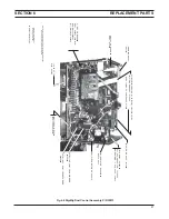
6. Connect the connector from the 14-pin receptacle
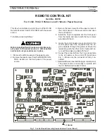
to the J4 header on the control PC board (see
Fig. 1). Make sure the connector is firmly con-
nected.
7. Reinstall left side panel and the upper control panel.
The power source is now ready to operate with
the HC-3B Remote Pendant Control.
Fig. 1. Control Board Assembly (located behind Control Panel)
J4 Header
Содержание Digimig Dual
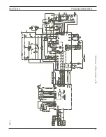
Страница 21: ...21 SECTION 4 TROUBLESHOOTING Fig 4 1 Schematic Diagram Dual Digimig 30914 L ...
Страница 22: ......
Страница 29: ...29 NOTES ...
Страница 30: ...30 NOTES ...

