background image

bt07d109

 15 

dpb1d1ea

7

MAINTENANCE

Regular maintenance is important for safe, reliable operation.

Only those persons who have appropriate electrical knowledge (authorized

personnel) may remove the safety plates to connect or carry out service,

maintenance or repair work on welding equipment.

Note!

All guarantee undertakings from the supplier cease to apply if the customer himself

attempts any work in the product during the guarantee period in order to rectify any

faults.

7.1

Check

up and cleaning 

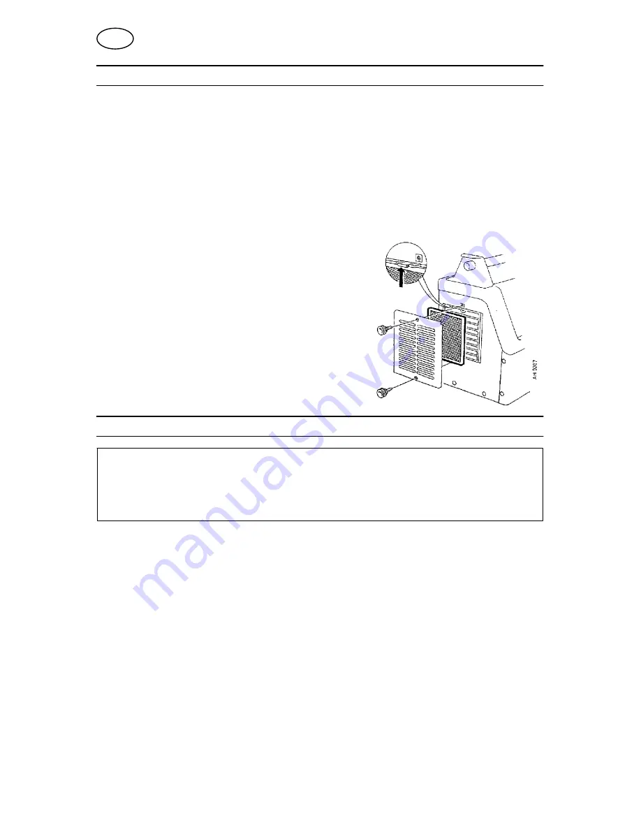
Clean the welding power source once a year using

dry compressed air (reduced pressure). The dust

filter is to be checked up and cleaned regularly. 

If the welding power source is used in a dusty and

dirty environment, the cleaning should be

performed more frequently.

For maximal service reliability it could be

advisable to let an authorised retailer service the

machine once a year.

8

ORDERING OF SPARE PARTS

DTE 255 is designed and tested in accordance with the international and European

standards IEC/EN 60974

1 and EN 50199. It is the obligation of the service unit which

has carried out the service or repair work to make sure that the product still conforms

to the said standard.

Spare parts may be ordered through your nearest ESAB dealer, see the last page of

this publication.

GB

Содержание Aristotig255 AC/DC DTE 255

Страница 1: ...GB Valid for serial no 810 to 246 0457 784 201 GB 031110 Aristotig 255 AC DC DTE 255 Instruction manual ...

Страница 2: ...nd connection 7 6 OPERATION 7 6 1 Controls and connections 7 6 2 Remote control unit 8 6 3 Protection against overheating 8 6 4 Control panel 8 6 5 MMA welding Hand welding electrodes 11 6 6 TIG welding 12 6 7 Forced disconnection 14 7 MAINTENANCE 15 7 1 Check up and cleaning 15 8 ORDERING OF SPARE PARTS 15 DIAGRAM 16 ORDERING NUMBER 17 SPARE PARTS LIST 18 ACCESSORIES 19 ...

Страница 3: ...acquainted with the operation of the welding equipment Incorrect operation of the equipment may lead to hazardous situations which can result in injury to the operator and damage to the equipment 1 Anyone who uses the welding equipment must be familiar with S its operation S location of emergency stops S its function S relevant safety precautions S welding 2 The operator must ensure that S no unau...

Страница 4: ...oth to take fumes and gases away from your breathing zone and the general area ARC RAYS Can injure eyes and burn skin S Protect your eyes and body Use the correct welding screen and filter lens and wear protective clothing S Protect bystanders with suitable screens or curtains FIRE HAZARD S Sparks spatter can cause fire Make sure therefore that there are no inflammable materials nearby NOISE Exces...

Страница 5: ...or the product can be found on page 19 3 1 Equipment DTE 255 is delivered with S Mains cable 3 m S Return cable 5 m S Gas hose S Hose clamps 4 TECHNICAL DATA DTE 255 Permissible load at 25 duty cycle MMA 60 duty cycle MMA 100 duty cycle MMA 250 A 30 V 200 A 28 V 165 A 26 V 100 duty cycle MMA 50 duty cycle TIG 60 duty cycle TIG 100 duty cycle TIG 165 A 26 V 250 A 20 V 225 A 19 V 170 A 17 V Setting ...

Страница 6: ...ss i e the degree of protection against penetration by solid objects or water Equipment marked IP23 is designed for indoor and outdoor use 5 INSTALLATION The installation must be executed by a professional WARNING This product is intended for industrial use In a domestic environment this product may cause radio interference It is the user s responsibility to take adequate precautions DTE 255 has m...

Страница 7: ...e The machine is now ready for use 6 OPERATION General safety regulations for the handling of the equipment can be found on page 3 Read through before you start using the equipment 6 1 Controls and connections Central connection A Mains switch ON OFF H Mains voltage ON LED B Connection for remote control unit J Welding voltage ON LED C Torch connector L Error Overheating LED D Connection for elect...

Страница 8: ... remote control unit is connected If the remote control is to include the whole current range the current must be set to max on the welding power source Max value The reference value set on the welding power source 6 3 Protection against overheating Three thermal cut outs prevent the power source being overloaded as a result of too high temperature If this should happen the welding current is inte...

Страница 9: ...sing the shift function 10 Potentiometer S For setting the welding current slope down 0 to 10 seconds 11 Potentiometer S For setting the gas postflow time 3 to 30 seconds 12 Potentiometer for setting the fre quency This potentiometer has double functions S For setting the pulse frequency between 0 3 and 300 Hz for pulsed welding with direct current S For setting the a c frequency between 30 and 30...

Страница 10: ...ly increases up to the set value during the set slope up time When you want to finish welding the contact is released and the current slowly decreases to the set slope down time Place the electrode against the workpiece Press in the torch trigger Tilt the torch a little lift and an arc is produced To stop release the torch trigger Position Two four stroke Two stroke means that the arc is struck wh...

Страница 11: ...ent using potentiometer 8 It is also possible to use pulsed welding current The settings are made in the same way as for pulsed TIG welding S Potentiometer 5 is used for stepless setting of the Hot Start function potentiometer 6 for stepless setting of the Arc Force function and thereby the control dynamics S Depending on the electrode type to be used direct current and polarity or one of the alte...

Страница 12: ...desired position If a foot operated remote control unit is to be used set switch 1 to position two stroke NB For direct current control over the foot operated remote control unit the potentiometer 7 and 10 must be set to position 0 A hand operated remote control unit can be used for both two stroke and four stroke to set the welding current S Select the desired striking method using switch 2 S Adj...

Страница 13: ...ng 200 2000 ms 3 The start current is 15 A 4 The slope up time is adjusted on the front panel 0 10 s 5 The pulse current is adjusted on the front panel 5 250 A 6 The background current is adjusted on the front panel 10 90 of the pulse current 7 The slope down time is adjusted on the front panel 0 10 s 8 At termination the current is pre set to 5 A 9 The gas postflow time is adjusted on the front p...

Страница 14: ...esulting in a somewhat higher noise level The arc is always struck by way of direct current which is then automatically switched over to alternating current Increased alternating current frequency gives a concentrated and stable arc suitable above all when a low amperage is used and when welding in extremely thin plate The displacement balance of the half wave in positive direction leads to increa...

Страница 15: ...r using dry compressed air reduced pressure The dust filter is to be checked up and cleaned regularly If the welding power source is used in a dusty and dirty environment the cleaning should be performed more frequently For maximal service reliability it could be advisable to let an authorised retailer service the machine once a year 8 ORDERING OF SPARE PARTS DTE 255 is designed and tested in acco...

Страница 16: ...Edition 031110 Diagram 16 dpb1e11a ...

Страница 17: ...pb1o11a Ordering no Denomination Type Notes 0301 035 880 Welding power source DTE 255 with central connection for the TIG torch 0301 035 881 Welding power source DTE 255 with OKC connection for the TIG torch 0457 784 990 Spare part list DTE 255 ...

Страница 18: ...DTE 255 Edition 031110 Spare parts list 18 dpb1s Item Qty Ordering no Denomination 1 1 0301 028 001 Grill 2 1 0301 054 001 Filter 3 3 0441 819 001 Screw 4 1 0301 027 001 Grill 5 1 0301 053 001 Filter ...

Страница 19: ...880 Return cable 0369 857 888 Foot control FS 002 0349 090 886 Cooling unit OCF 2D 0457 216 881 TIG torches HW 26 R 4 m with OKC connection HW 26 R 4 m with central connection HW 20 4 m with OKC connection HW 20 4 m with central connection 0588 000 738 0588 000 740 0588 000 744 0588 000 746 ...

Страница 20: ...nal AB Gothenburg Tel 46 31 50 90 00 Fax 46 31 50 93 60 SWITZERLAND ESAB AG Dietikon Tel 41 1 741 25 25 Fax 41 1 740 30 55 North and South America ARGENTINA CONARCO Buenos Aires Tel 54 11 4 753 4039 Fax 54 11 4 753 6313 BRAZIL ESAB S A Contagem MG Tel 55 31 3369 4333 Fax 55 31 3369 4440 CANADA ESAB Group Canada Inc Missisauga Ontario Tel 1 905 670 02 20 Fax 1 905 670 48 79 MEXICO ESAB Mexico S A M...

Отзывы: