


6
The magnetic element is permanently magnetic and
incorporates highly oriented Erium 25 (Ceramic VIII)
magnet material. It requires no external power source.
AC power requirements for the drive motor
are stipulated on the nameplate fixed to the
motor housing.
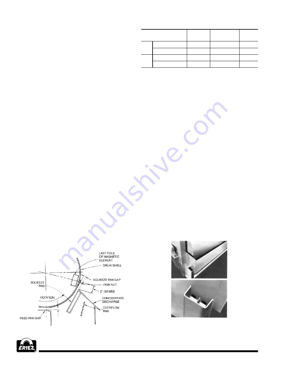
MAGNET ADJUSTMENT
For initial operation or after replacement of parts in
the drum and hub, the magnet position should be
checked. If adjustment of the magnet is required
the following procedure should be followed:
Loosen both shaft clamps. On the end of the shaft
opposite the drive motor, a hole is provided for
adjustment of the magnet with the use of a 1-1/4"
(32 mm) diameter bar. The colored area on the end
of the shaft indicates the approximate position of the
magnetic area. Using this as a guide, slide a small
iron nut across the drum surface until it is attracted
and held by the trailing edge of the magnet. Once you
have done this, adjust the position of the magnet until
the iron nut is approximately 2" (50 mm) above the
discharge lip. Making sure the magnet is held in place,
tighten the shaft clamps (See Figure 3).
The magnet setting as described above should result
in a satisfactory point of discharge; however, slight
adjustment up or down can be made from the normal
position to obtain optimum results. In which the
magnitite is in the horizontal plain (stick outward)
at the discharge lip.
Operation
FIGURE 3
Model
HMDA
Self-Leveling
CL1
36" ø
Feed Pan Gap
1-1/4" (32)
1-1/2" (38)
2" (51)
Squeeze Pan Gap
1-1/4" (32)
1" (25)
2" (51)
48" ø
Feed Pan Gap
1-1/4" (32)
1-3/4" (44)
2" (51)
Squeeze Pan Gap
1-1/4" (32)
2" (51)
2" (51)
FEED AND SQUEEZE‑PAN ADJUSTMENT
Feed and squeeze-pan clearances are set at the
factory, but are adjustable by moving the drum
horizontally or vertically as required. Slotted shaft
clamp mounting holes provide room for lateral
movement and vertical adjustment is accomplished
by adding or removing shims beneath the shaft
and frame.
WATER LEVEL AND OVERFLOW ADJUSTMENT
It is very important in this type of separator to
maintain the proper water level. Overflow volume
should be from 40% to 50% of total tailings flow.
This is controlled by the size of the tailings discharge
openings and the volume of feed. Since the feed
should be constant, adjustment is made by changing
the size of the tailings reducer bushings. Restricting
the openings will increase overflow and vice versa.
An external water level overflow weir is provided
on HMDA Models. A proper water level can be
maintained when water is overflowing the weir
located between the holes in the tank side plate
(See Figure 4).
FIGURE 4