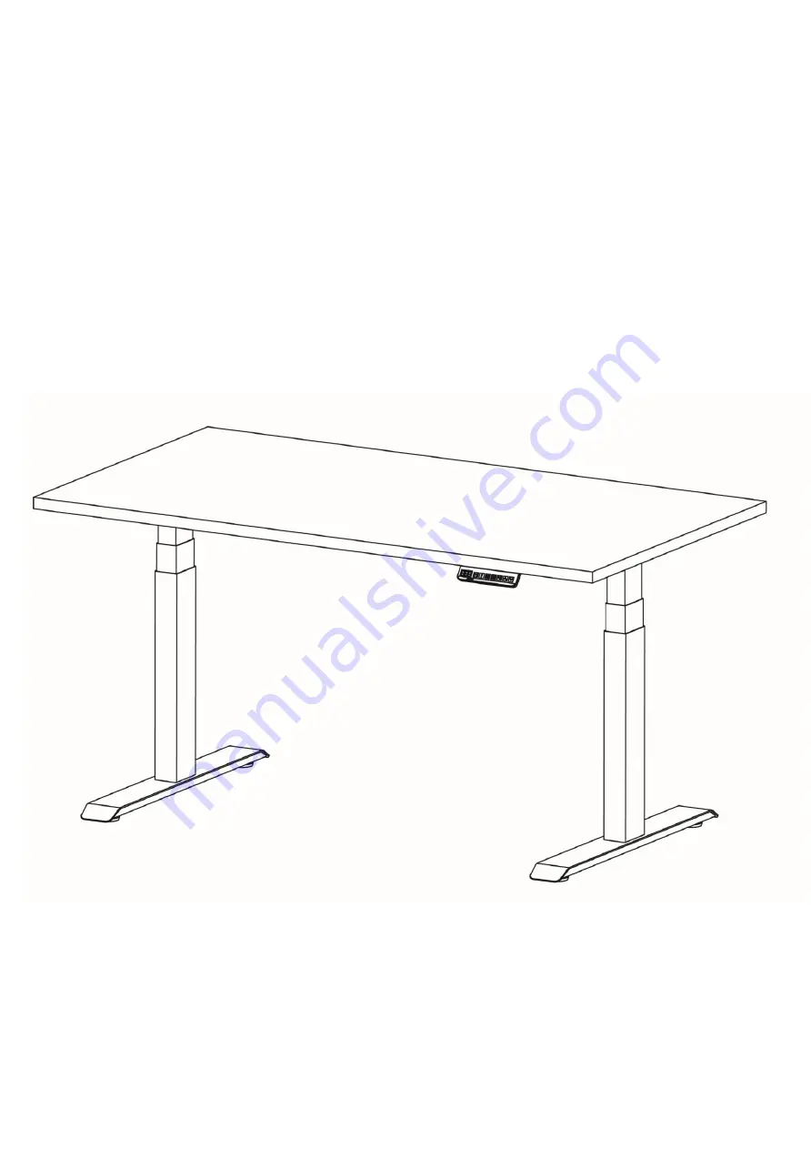
ELECTRIC HEIGHT ADJUSTABLE TABLE
Assembly and Operation Instructions
Страница 1: ...ELECTRIC HEIGHT ADJUSTABLE TABLE Assembly and Operation Instructions ...
Страница 2: ...n Cable 2 9 Power Cord 1 10 Cable Clip 8 11 Levelling Foot 4 12 Hex Socket Screws Pack A M6X12mm 16 Part Name Qty 13 Hex Socket Screws Pack B M6X35mm 4 14 Hex Socket Screws Pack C M6X14mm 6 15 Wood Screws Pack D M5X16mm 8 16 Hex Socket Screws Pack E M6X10mm 8 17 4mm Allen Key 1 18 Phillips Screwdriver or Electric Hand Drill Not included ...
Страница 3: ...art 3 into the End Frame Part 1 as shown in the diagram Note Orientate the center screw hole of the End Frame flushed to the top surface of the Lift Column Align the edge holes of the Lift Column with the holes in the End Frame Insert and fasten loosely using 4 screws from Pack A with the supplied 4mm Allen Key Part 17 Do not tighten the screws yet Repeat the same process for the other Lift Column...
Страница 4: ...Column Insert the Side Bracket Part 4 into the End Frame Part 1 and align the screw holes as shown Note You may need to gently tap the bracket into place to align the screw holes Insert and fasten using 2 screws from Pack B Repeat the same process for the other Lift Column If there is difficulty fastening the screws it may be because some of the earlier installed screws were fastened too tightly L...
Страница 5: ...p and its work surface Place the two assembled Lift Columns Part 3 on the bottom surface of the table top and insert the Cross Rails Part 2 into the End Frames Part 1 Ensure the Cross Rail slots face inwards Check that the frame assembly is sitting flat on the table top and tighten the screws in STEP 2 in a criss cross pattern If the frame assembly does not sit flat loosen screws installed in step...
Страница 6: ...e frame to the table top Check and make sure that the supplied wood screws in Pack D are not too long for the table top Wood screws which are too long can puncture and damage the work surface If the wood screws are too long purchase shorter wood screws which fits your table top Maximum width of the frame is 180cm Attach the Control Box Part 6 by sliding it into the bracket welded to the End Frame ...
Страница 7: ...t 9 to the Control Box Secure all cables neatly using the Cable Clips provided Part 10 Ensure the Cross Rails Part 2 are positioned evenly within the End Frames Part 1 Insert and fasten using 8 screws from Pack E in a criss cross pattern to fix the Cross Rails in position Note If the cable cover tray is purchased Align the cable cover tray slots to the screw holes before fastening the screws STEP ...
Страница 8: ...lumns and using the feet as pivot points Adjust the Levelling Feet Part 11 as needed Plug the Power Cord Part 9 into the mains and turn on the power Reset the frame before use See Operation Guide for the Reset Procedure Make sure no obstacles are above or below the table Make sure the table is not touching any walls Make sure all cords have the appropriate length to accommodate changes in height ...
Страница 9: ...old the down arrow button to move the table down to the desired height release to stop Memory Preset Depending on the handset s model it may store up to 3 or 4 height presets Use the up and down arrow buttons on the handset to reach the desired height Press the M button and the handset displays S Press any of the numeral buttons to preset the height setting to that corresponding number Pressing a ...
Страница 10: ...Sedentary countdown ranges between 30 mins to 5 hours in steps of 30 mins To cancel sedentary mode Press buttons 1 and 3 together and handset displays X Xh X denotes a numeral Press the down arrow button till the handset displays 0 0h The setting will automatically exit by itself after 2 seconds Set custom maximum and minimum height good for obstacle avoidance Set the maximum height Move the table...
Страница 11: ...ately 5 seconds Release the buttons when you hear a buzzer sound signaling the cancellation of the custom minimum height Anti Collision Sensitivity Unit Of Height Setting Please kindly contact technical support Warning Do not move the table continuously for more than 2 minutes without at least an 18 minutes break interval To avoid overloading the transformer there is an overload protection program...
Страница 12: ...s before using E11 21 Motor M1 M2 is not connected Plug M1 M2 motor cable connectors into the control box E12 22 Motor M1 M2 current sampling error Reconnect M1 M2 motor cable connectors into control box If problem persists check with technical support E13 23 Phase loss or phase line disconnected from motor M1 M2 Reconnect M1 M2 motor cable connectors into control box If problem persists check wit...
Страница 13: ...mer Adjustable anti collision system Custom max and min height set up Short circuit protection Overheat protection Error Code Key Code Meaning Suggested Actions E40 Series connection error Reconnect all cable connectors into control box If problem persists check with technical support E41 Series signal error Reconnect all cable connectors into control box If problem persists check with technical s...
Страница 14: ...Any other use is at user s risk Under no circumstances does the manufacturer accept warranty claims or liability claims for damages caused from improper use or handling of the table frame Make sure no obstacles are above or below the table Make sure the table is not touching any walls Make sure all cords have the appropriate length to accommodate changes in height WARNING PINCHPOINT USE LIABILITY ...