


SR2 Technical Manual EN
Indice : C
25/03/2019
Firmware v2.9
8 / 31
ERECA SAS - 75 rue d'Orgemont, 95210 St Gratien France
T : +33 1 39 89 76 23 W : www.ereca.fr
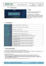
2.3.2 General Purpose OUT
For forward product compatibility the GP OUT section is split on two kind of connectors.
Outputs 1 and 2
are shared with each Serial signal transmission RJ 45 terminal, labeled " Serial/Gpio ".
These outputs are on floating dry contact relays with 50 Volts AC/DC and 0.25A switching capacity.
The relay is open if the corresponding remote input is not triggered.
1
8
1: GND
2: GP IN
3: RX RS 422 – or RX RS 232
4: TX RS 422 – or TX RS 232
5: TX RS 422 +
6: RX RS 422 +
7: GP OUT
8: GP OUT
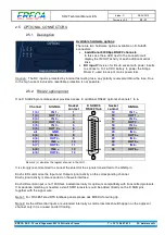
Outputs 3 to 8
are on one D-SUB 15 terminal female socket. These outputs are also on floating dry contact
relays with 50 Volts AC/DC and 0.25A switching capacity. The relay is also open if the corresponding
remote input is not triggered.
Ground and power pins are available on the connector to ease interfacing with others machines especially if
the driven machine need a voltage information rather than a contact closure.
The 12 volts output of the Stage Racer 2 is protected against external short circuit by an internal 100mA
resettable fuse (polyswitch) common to GPI and GPO sockets.
Relay
N°
SIGNAL
Socket
contact
D SUB 15
GP OUT
Socket
contact
SIGNAL
3
GP OUT 3a
1
1
9
8
15
9
GP OUT 3b
4
GP OUT 4a
2
10
GP OUT 4b
5
GP OUT 5a
3
11
GP OUT 5b
6
GP OUT 6a
4
12
GP OUT 6b
7
GP OUT 7a
5
13
GP OUT 7b
8
GP OUT 8a
6
14
GP OUT 8b
GND (0V)
7
15
+ 12V 100 mA
GND (0V)
8
Each GPI can be affected to one or Multiple GPO by using the GPIO routing grid of the Stage racer 2.


