�
�
�
��������������������
�
��
�
��
�
��
�
�
�
��������������������
�
��
�
��
�
��
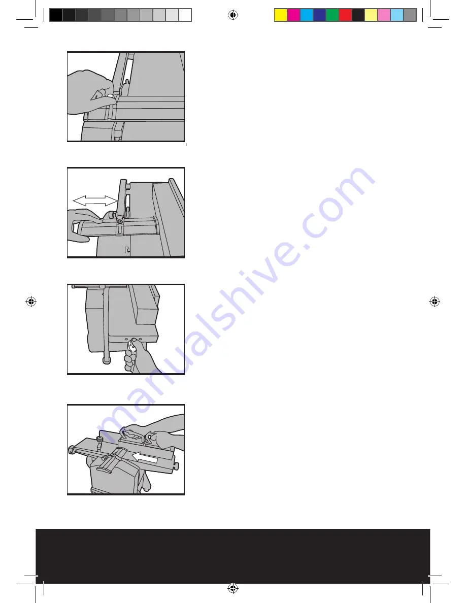
1.3 Setting the blade guard (9). (See Fig 18-
19)
1) Loosen the blade guard locking knob (10).
2) Pull back the blade guard (9).
3) Set the workpiece against the guide fence (8).
4) Slide the blade guard (8) towards the workpiece
(leaving a small gap of a few millimetres).
5) Re-tighten the blade guard locking knob (10) to
secure.
Caution:
When the machine is not in use the
plug should be removed from the mains socket
and the blade guard (9) should be set so that it
covers the whole of the cutter assembly so as to
reduce the risk of injury.
1.4 Setting the depth of cut. (See Fig 20)
The depth of cut is the amount of material
removed from the workpiece with a single pass
over the cutter-block. It is set by the in-feed table
moving up / down in relation to the out-feed table
(this is fixed).
Note:
The maximum cut of 3mm should only be
utilized on softer woods. The planer thicknesser
will give a much better quality finish on harder
woods such as oak if less material is removed on
each pass.
1) Turn the cut depth control knob (5) clockwise
to reduce the depth of cut and anti-clockwise to
increase the depth of cut.
2) The scale to the left of the in-feed table shows
the amount of material that will be removed per
pass.
3) 1 relates to approximately 1mm, 2 relates to
approximately 2mm etc.
1.5. Planing mode: Making a pass with the
workpiece. (See Fig 21)
Once everything is set as needed the planer
thicknesser can now be safely operated.
1) Ensure that the cutter block is free from foreign
objects (including the workpiece to be planed).
2) Connect the planer thicknesser to the mains
supply.
3) Turn the planer on with the green “1” button
(1).
4) Allow the planer to reach its maximum speed.
5) Place the workpiece onto the in-feed table and
ensure that the workpiece stays parallel with the
in-feed table for the whole pass.
6) Slowly push the workpiece forward (over the
Fig 19
Fig 18
Fig 20
Fig 21
BTP210F-M-070928.indd 16
2007-9-28 13:35:57


