8” THICKNESS PLANER
ASSEMBLY
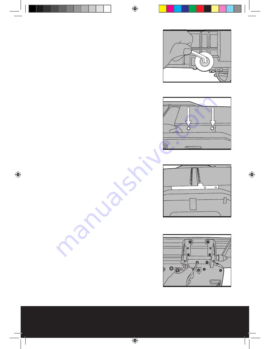
1. Fitting the rubber (anti-vibration) feet
(See Fig 1):
1) Carefully turn the machine upside down, taking
care not to damage the in-feed / out-feed beds.
2) Fit the washers over the hex bolts and push
both through the holes in the rubber feet.
3) Fit the feet / bolts to the holes provided (1 on
each corner of the machine).
4) Secure using a 6 mm hex key.
2. Fitting the guide fence (8 )(See Fig 2-4):
1) Locate the 2 x guide fence mounting holes
situated on the side of the planning out-feed table
(13).
Then place the safety guard plate. (Fig 3)
2) Line up the 2 x mounting holes on the guide
fence (8) with those situated on the out-feed table
(13).
3) Fit the 2 x supplied hex head screws through
both sets of holes and tighten to secure.
Note:
Do not over-tighten the screws as this will
cause un-wanted damage to the aluminium out-
feed table. Rather just tighten until the fence is
secured.
Fig 2
Fig 1
Fig 3
Fig 4
BTP210F-M-070928.indd 11
2007-9-28 13:35:55


