background image

S

ERVICE


28 


4-1 

VSC Board 


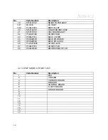
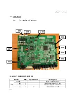
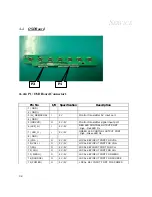
4-1.1    The Location of Connector 


4-1.2 J17 : RS232C CONNECTOR 


Pin No 

I/O 

Specification 

Description 

1 (GND ) 


RS232C GROUND PORT 

2 ( Rx ) 


RS232C RECEIVE DATA PORT 

3 ( Tx ) 


RS232C TRANSMIT DATA PORT 

J17 

4 ( 5V ) 

5V 

RS232C POWER PORT 

J18


J17


J15


J20


J19


J16


J13


J14


J24


Содержание EPT4220AP

Страница 1: ...NCH PLASMA TV Rev 00 REV Description Change Page Author Date Approval 1 Research Engineer Jan 13 2005 Jan 13 2005 RIVISION HISTORY T T TE E EC C CH H HN N NI I IC C CA A AL L L S S SE E ER R RV V VI I...

Страница 2: ...w major system assembly components description and the Troubleshooting making explanations on how to detect errors It also includes a flow chart for checking or correcting faults No warranty or repres...

Страница 3: ...Parts List 2 7 3 Procedure of Disassembly 3 1 3 1 Disassemble Back Cover and Jack Housing 3 1 3 2 Disassemble Back Bracket Parts and Board 3 2 3 3 Disassemble PDP Module 3 3 3 4 Disassemble Front Filt...

Страница 4: ...Defects 6 5 7 Function Test Alignment Procedure 7 1 7 1 Test Equipment 7 1 7 2 Test Condition 7 2 7 3 Test Display Modes and Pattern 7 3 7 4 Function Test and Alignment Procedure 7 4 7 5 Cleaning 7 5...

Страница 5: ...del of EPT 4220AP PDP TV There are nine topics in this manual and you can immediately identity the problem through the manual This manual is for the technicians and people who have the electronic back...

Страница 6: ...r plug and play convenience 1000 cd m2 higher brightness and 3000 1 Contrast Ratio 1024 768 XGA 75Hz resolution support Wide compatibility with 15 7 70KHz for horizontal scan Multi functional OSD On S...

Страница 7: ...DP42V6 Screen Size 42 diagonal Dimension Outline 1006 W 598 H 61 D 1mm Active Area 920 1 W 518 4 H 0 5mm Technology AC Plasma Technology Display Pixels 852 480 Brightness 1000 cd m2 typ Contrast Ratio...

Страница 8: ...olors Compatibility Range Maximum Pixel Frequency 78 75MHz XGA 75Hz Horizontal Frequency 31KHz 70KHz SVGA Vertical Refresh 50Hz 75Hz 1 2 3 Electrical Power Power Supply Built in Power Supply AC220 240...

Страница 9: ...1 Temperature Operating 0 C 40 C Neglect altitude Non Operating 20 C 60 C For all altitude 1 3 2 Humidity Operating 20 80 Without condensation Non Operating 10 90 Without condensation 1 3 3 Pressure O...

Страница 10: ...___________ This section provides the package and exploded overview replaceable parts list and recommendation parts list for the 42 PDP TV You can place an order for correct parts in the recommendati...

Страница 11: ...MANUAL _ EPT 4220AP ERAE ELECTRONICS 11 2 1 Package Overview...

Страница 12: ...placement Parts List No Code Number Description 1 86AELB307 TOP BOX 42N 2 93CELB304 93CELB305 PAD TOP L R 3 92CELB309 PE BAG 42N 4 93CELB302 93CELB303 PAD DOWN L R 5 86AELB308 BOTTOM BOX 42N 6 S150129...

Страница 13: ...MANUAL _ EPT 4220AP ERAE ELECTRONICS 13 2 2 Exploded Overview 2 2 1 PDP SET OVER VIEW...

Страница 14: ...SERVICE 14 2 2 2 PDP MODULE OVERVIEW...

Страница 15: ...TOP X 10 71AELP355 FRAME TOP Y 11 S150143161 SPEAKER ASSY 12 S150113161 A V ASSY 12 1 71FELP438 SHIELD CASE T 12 2 S150141161 A V PCB ASSY 12 3 71FELP439 SHIELD CASE A V B 12 4 70AELM527 KNOB GUIDE A...

Страница 16: ...C BOARD ASSY 22 71GELP399 COVER SUB 23 71BELP374 BACK COVER 24 70CELM530 BACK SP OSD R 25 70CELM529 BACK SP AUD L 26 71AELP3565 COVER JACK 27 71AELP376 COVER PCB 28 70AELM528 DECORATION SP L R 2 2 3 2...

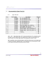
Страница 17: ...0 1 FOR 50 SW 10 3501Q00150A BOARD ASSEMBLY 42 MULTI UNICON PSU CM 11 6631Q39008F CONNECTOR ASSEMBLY 3 96MM 8PIN 880MM AMP PSU_Z BD CM 12 6631Q39025A CONNECTOR ASSEMBLY 3 96MM 10PIN AMP 150MM PSU Y B...

Страница 18: ...NSERT 42V6 TOP 2 YSUS ASSY HAND INSERT 42V6_4 L 3 POWER SUPPLY ASSEMBLY 42 MULTI UNICORN PSU 4 ZSUS ASSY HAND INSERT 42V6 5 YDRV ASSY HAND INSERT 42V6 BOTTOM 6 XRLT ASSY HAND INSERT 42V6 XL 7 CTRL ASS...

Страница 19: ...MANUAL _ EPT 4220AP ERAE ELECTRONICS 19 9 VSC BOARD ASSY 10 Tuner B D Assy...

Страница 20: ...TV Before you begin any of these procedures be sure to turn off the power and other attached devices then disconnect the power cable from the electronically outlet Moreover when you disassemble the P...

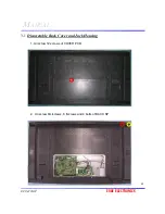
Страница 21: ...MANUAL _ EPT 4220AP ERAE ELECTRONICS 21 3 1 Disassemble Back Cover and Jack Housing 1 Unscrew 12 screws of COVER PCB 2 Unscrew 8m screws 8 t screws and 4 bolts of BACK SP...

Страница 22: ...SERVICE 22 3 Unscrew 19 m screws of BACK COVER 4 Unscrew 7 m screws 6 t screws 1 nut COVER JACK...

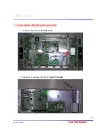
Страница 23: ...crews of BRKT PCB 2 Unscrew 8 screws of VSC TUNNER BOARD 4 Unscrew 4 m screws of Back Bracket Cooling PAN 5 Unscrew 2 m screws of Back Bracket Power and Tuner PCB 6 Unscrew 4 m screw of Tuner Board PC...

Страница 24: ...SERVICE 24 3 Unscrew 2 m screws of BRKT RS 2 t screws of KNOB GUIDE OSD 4 t screws of KNOB GUIDE AUD 4 Unscrews 8 t screws of SPEAKER ASSY RS 232C BOARD...

Страница 25: ...MANUAL _ EPT 4220AP ERAE ELECTRONICS 25 5 Unscrews 24t screws of FRAME TOP X Y FRAME TOP X TOP FRAME TOP X BOTTOM Use at FRAME TOP X TOP Use at FRAME TOP X BOTTOM...

Страница 26: ...SERVICE 26 3 3 Disassemble PDP Module 1 Unscrew 12 m screws of PDP MODULE 3 4 Disassemble PDP FILTER GLASS 1 Unscrew 32 t screws of FRAME BOTTOM X Y 1 1 2 2...

Страница 27: ...EPT 4220AP ERAE ELECTRONICS 27 CHAPTER 4 Function of Boards This section provides each connector location on boards signal and function of each board They will be useful for your detecting the defecti...

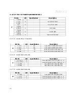
Страница 28: ...tion of Connector 4 1 2 J17 RS232C CONNECTOR Pin No I O Specification Description 1 GND RS232C GROUND PORT 2 Rx I RS232C RECEIVE DATA PORT 3 Tx O RS232C TRANSMIT DATA PORT J17 4 5V I 5V RS232C POWER P...

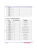
Страница 29: ...4 RB O LVDS OUT 1 5 RB O LVDS OUT 1 6 GND 7 RC O LVDS OUT 2 8 RC O LVDS OUT 2 9 RCLK O LVDS CLOCK 10 RCLK O LVDS CLOCK 11 RD O LVDS OUT 3 12 RD O LVDS OUT 3 13 GND 14 GND 15 NC 16 NC 17 NC 18 NC 19 G...

Страница 30: ...LOCAL KEY INPUT PORT FOR POWER 2 SOURCE I 5V 0V LOCAL KEY INPUT PORT FOR SOURCE 3 MENU I 5V 0V LOCAL KEY INPUT PORT FOR MENU 4 CH I 5V 0V LOCAL KEY INPUT PORT FOR CH 5 CH I 5V 0V LOCAL KEY INPUT PORT...

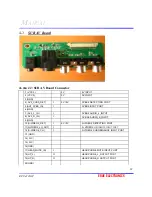
Страница 31: ...GND 3 SCART_G O SCART RGB_G 4 GND 5 SCART_B O SCART RGB_B 6 GND 7 SCART FB O SCART FB 8 GND 9 H_CVBS_L_OUT O HALF SCART CVBS L OUT 10 GND 11 H_CVBS_R_OUT O HALF SCART CVBS R OUT 12 GND 13 F_CVBS_L_OU...

Страница 32: ...ion 1 VCC5 5V 5V INPUT 2 VCC5 5V 5V INPUT 3 GND 4 AV2_CVBS_DET I 5V 0V CVBS2 DETECTING PORT 5 AV2_CVBS_IN I CVBS2 INPUT PORT 6 GND 7 AV2_L_IN I CVBS2 AUDIO_L_INPUT 8 AV2_R_IN I CVBS2 AUDIO_R_INPUT 9 G...

Страница 33: ...I 5V 0V AC POWER DETECT PORT AC INPUT DETECTING AC POWER ON High AC POWER OFF LOW Turn off the power by power sequence to stabilize PDP MODULE in case of power breakdown 2 RL ON O 5V 0V RELAY CONTROL...

Страница 34: ...CONNECTOR 1 Pin No I O Specification Description 1 VCC12 I 12V 12V INPUT 2 VCC12 I 12V 12V INPUT 3 VTT5 I 5V 5V INPUT 4 GND 5 AMP_L_OUT I AMP_L_OUTPUT 6 GND 7 AMP_R_OUT I AMP_R_OUTPUT 8 GND 9 S_MUTE I...

Страница 35: ...3 SCART_G O SCART RGB_G 4 GND 5 SCART_B O SCART RGB_B 6 GND 7 SCART FB O SCART FB 8 GND 9 H_CVBS_L_OUT O HALF SCART CVBS L OUT 10 GND 11 H_CVBS_R_OUT O HALF SCART CVBS R OUT 12 GND 13 F_CVBS_L_OUT O F...

Страница 36: ...ORT 2 24V I 24V Audio AMP POWER INPUT PORT 3 GND 0V Audio AMP POWER GROUND PORT J3 4 GND 0V Audio AMP POWER GROUND PORT 4 2 6 J1 Audio Out Connector Pin No I O Specification Description 1 R_OUT1 O Aud...

Страница 37: ...I CVBS2 INPUT PORT 6 GND 7 AV2_L_IN I CVBS2 AUDIO_L_INPUT 8 AV2_R_IN I CVBS2 AUDIO_R_INPUT 9 GND 10 S VIDEO2_DET I 5V 0V S VIDEO2 DETECTING PORT 11 S VIDEO2_LU_OUT I S VIDEO2 LUMINANCE INPUT PORT 12 S...

Страница 38: ...ED LED CONTORL OUTPUT PORT High Red LED On 7 LED_G I 5V 0V GREEN LED CONTORL OUTPUT PORT High Green LED On 8 GND 9 VOL O 5V 0V LOCAL KEY INPUT PORT FOR VOL 10 VOL O 5V 0V LOCAL KEY INPUT PORT FOR VOL...

Страница 39: ...igh Green LED On 2 LED_R I 5V 0V RED LED CONTORL OUTPUT PORT High Red LED On 3 IRRCVR O 5V 0V Monitor transmitter s ignal input port 4 GND 5 5V_REMOCON I 5V Monitor transmitter 5V input port P2 6 GND...

Страница 40: ...ansmitter signal input port 4 GND 5 5V_REMOCON I 5V Monitor transmitter 5V input port 6 GND 4 6 RS232C Board 4 6 1 J3 RS 232 Connector Pin No I O Specification Description 1 GND 0V RS232C GROUND PORT...

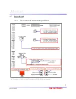
Страница 41: ...MANUAL _ EPT 4220AP ERAE ELECTRONICS 41 4 7 Power Board 4 7 1 The Location of Connector and Specification...

Страница 42: ...2V SIGNAL CLOCK 3 SLE O 12V SIGNAL ENABLE 4 SDATA O 0V SIGNAL DATA 5 GND 0V 6 GND 0V 7 GND 0V 8 GND 0V 9 R2 O TMDS RECEIVE 2 10 R2 O TMDS RECEIVE 2 11 GND 0V 12 R1 O TMDS RECEIVE 1 13 R1 O TMDS RECEIV...

Страница 43: ...GND 0V 5 GND 0V 6 VA O REFER TO THE MODULE LABEL 7 GND 0V P1 8 5V O 5V 4 8 4 P5 Pin No I O Specification Description 1 VS O REFER TO THE MODULE LABEL 2 VS O REFER TO THE MODULE LABEL 3 VS O REFER TO...

Страница 44: ...apter provides technicians and people who have an electronic background a primary description about maintaining the product Moreover you can get the appropriate operation to solve some complicated pro...

Страница 45: ...MANUAL _ EPT 4220AP ERAE ELECTRONICS 45 5 1 Equipment Needed EPT 4220AP Pattern Generator Volt meter Screw Driver...

Страница 46: ...s Power ON NO Display Performance OK NO A Power Circuit Troubleshooting B Display Troubleshooting TV Display OK Function adjust OK C T V Troubleshooting NO N O D Function Troubleshooting Audio functio...

Страница 47: ...Is LED not light Check Power Cable Check AC Line Fuse NO Change Power Board NO No Image Check Panel Link Power Cables YES NO NO YES YES YES YES YES YES YES Check Vs Va NO Change Control Board Change Y...

Страница 48: ...nge VGA DVI cable NO Change VSC Board NO Is PDP line defective Change panel link cable YES F PDP Module Troubleshooting NO Change panel link cable NO Change VSC Board F PDP Module Troubleshooting NO R...

Страница 49: ...rce Changevideo cable NO Change VSCBoard NO Is PDP line defective Changepanel link cable YES F PDP Module Troubleshooting NO Changepanel link cable NO Change VSCBoard F PDP Module Troubleshooting NO C...

Страница 50: ...anel link cable YES F PDP Module Troubleshooting NO Change panel link cable NO Change VSC Board Check Input source YES Check video cable NO NO Change panel link cable Dose screen have noise Check Inpu...

Страница 51: ...color or tint menu YES Change VSC Board NO Change panel link cable NO Change VSC Board Change RF cable YES Change Tuner Board NO NO Change VSC Board No TV audio Do Mute off YES Change audio out speak...

Страница 52: ...bleshooting Start NO No Trouble Found End Function Troubleshooting Is Menu OSD displayed Change Remote controller Change OSD Board OSD cable NO Change VSC Board NO Is Menu function working NO Change V...

Страница 53: ...Volume Equalizer adjustable No Trouble Found End Audio Troubleshooting Have Sound Do Mute off NO Check Audio power cable NO Change Speaker Change VSC Board NO YES YES NO NO YES YES YES YES YES Change...

Страница 54: ...Horizontal line defect YES Partial defect No Trouble Found End Audio Troubleshooting Vertical line defect YES YES YES NO NO NO YES YES Make sure Power and Signal cable is OK F 1 Vertical Line Defect Y...

Страница 55: ...ct Troubleshooting Start Vertical Line Troubleshooting YES YES NO Make sure Power and Signal cable is OK YES No Trouble Found End Replace X Board Replace Control Board NO YES YES Replace X Board Repla...

Страница 56: ...Line Defect Troubleshooting Start Horizontal Line Troubleshooting YES YES NO Make sure Power and Signal cable is OK YES No Trouble Found End Replace Y Driver Board NO Other Vertical line defect Repla...

Страница 57: ...ooting Start Partial Defect Troubleshooting YES YES NO Make sure Power and Signal cable is OK YES Center screen is darker then Edge screen No Trouble Found End Replace Y Driver Board Replace Y Sustain...

Страница 58: ...SERVICE 58 CHAPTER 6 Panel Specification This chapter provides the 42 PDP panel specification including optical characteristics and dot defects All information is for your reference...

Страница 59: ...tripes Number of gradations 256 steps for PC RGB Peak brightness Typical 1000cd 1 25 white window pattern at center Power consumption Typical 220W note1 Full white pattern Contrast ratio Typ 3000 1 In...

Страница 60: ...e Range Dependent on the characteristics of each PDP 55 65 V Voltage Stability 1 0 Average current Varied correspondence to the image 0 005 0 5 1 4 Amean Ripple Noise 600 mVp p Note Voltage should be...

Страница 61: ...white 0 01 Avrg 0 010 Office Room CRBR 150 Lux at center 40 1 50 1 Contrast Ratio Dark room CRDR 1 25 White window 1800 1 2700 1 Measure the dark position of panel while Window pattern is On state Vie...

Страница 62: ...is 5mm or shorter N 0 for the stain of which longer axis length is longer than 5mm D 50 mm Quality decision point Cell defect definition 1 Non Ignition Dot Dark Defect is defined as A cell of which m...

Страница 63: ...is excluded in full screen defect The decision distance is 1 6m 3H away from the panel intensity of illumination is between 100 lux and 200 lux Cell defects do not increase or progress as time goes De...

Страница 64: ...s chapter provides equipment conditions patterns and procedure needed for Function Test and Alignment It also includes compatible modes All information is for your reference 7 1 Test Equipment Pattern...

Страница 65: ...ed up for at least 2 hours with the following conditions a In room temperature b With full white screen c With cycled display modes RESOLUTION H Freq KHz V Freq Hz 31 47 60 37 86 72 640 480 37 50 75 7...

Страница 66: ...DVD 576I 720 480 31 47 59 94 SDTV 480P 720 576 31 25 50 00 HDTV 576P 1280 720 37 50 50 00 HDTV 720P 1280 720 45 00 60 00 HDTV 720P 1920 1080 28 12 50 00 HDTV 1080I 1920 1080 33 75 60 00 HDTV 1080I RG...

Страница 67: ...ary Horizontal Vertical Thickness Horz And Vert Position of video should be adjustable to be within the screen frame Figure3 4 R G B Color Performance R G B Color Intensities Contrast of each R G B co...

Страница 68: ...SERVICE 68 Horizontal Vertical Thickness Pattern Figure 3 R Color Pattern Figure 4 G Color Pattern Figure 5 B Color Pattern Figure 6...

Страница 69: ...use button to move to Picture menu Press button to move to Custom adjust and press Enter to select Use button to the desired category to control and use button to adjust the setting Use to select betw...

Страница 70: ...to the desired category to control and use button to adjust the setting Use to select between Auto Adjustment Phase H Position V Position Test Pattern Any Pattern with supporting display mode 7 4 5 C...

Страница 71: ...ERAE ELECTRONICS 71 CHAPTER 8 Firmware Upgrade Procedure This chapter provides the equipment needed setup and upgrading procedure for firmware upgrade According to the instruction you could finish FW...

Страница 72: ...8 1 Equipment Needed RS232 Cable P N PC Personal computer Firmware Upgrade Program RS232 Cable 8 2 Setup Procedure 1 Connect RS232 cable between RS232 connector of PDP TV and COM1 of PC 2 Connect PDP...

Страница 73: ...MANUAL _ EPT 4220AP ERAE ELECTRONICS 73 8 3 Upgrade Procedure 1 Find FlashExpress exe program in the computer 2 Run FlashExpress exe program...

Страница 74: ...SERVICE 74 3 Click where mouse is located and find a directory which WARE3 INF file is in And click OK 4 Check if the port is COM1 and the protocol speed is 115200...

Страница 75: ...MANUAL _ EPT 4220AP ERAE ELECTRONICS 75 5 Click Flash to upgrade program...

Страница 76: ...ERAE Electronics YY Last two numbers of the year ex 2003 03 2004 04 M number of month ex January 1 March 3 SSSSS Serial code from 00001 A Major change A revision 0 B revision 1 EX ER04100075A This lab...

Отзывы: