background image


epur | USER’S MANUAL 

 www.epur.io    - - | 60 | - -    [email protected]  


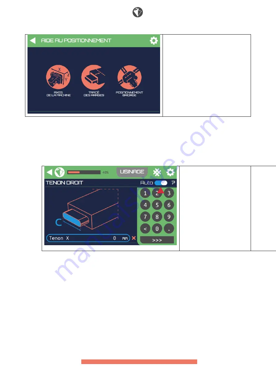
POSITIONING ASSISTANCE 


MACHINE AXES – SHOULDER LINES – 

CLAMPING POSITIONING 


4.


The first parameter is the option for automatic centering; if activated, you 

will only be asked the dimensions of the beam and tenon. The tenon will be 

automatically centered on the beam.  Should you wish to carry out an off-

centre tenon, deselect this option. 


MACHINING 


STRAIGHT TENON Auto 


X Tenon         0 mm 


5.


The question mark symbol makes it possible to obtain information  on the 

dimensions automatically managed by the programme. 

Содержание OAKBOT EOX 4.2 Series

Страница 1: ...DOCUMENT epur User s Manual OAKBOT EOX series 4 2 Original Manual...

Страница 2: ...dimensioning assemblies 15 Safety 15 Instructions for use 21 1 Aim 21 2 Starting up the OAKBOT 21 3 Shutting down the machine 23 4 Milling Tools 24 5 Calibration 30 6 Preparing the pieces of wood 38...

Страница 3: ...your digital milling machine in complete safety After Sales Service You can contact the After Sales Service by e mail at the following address support epur io by surface mail at the following address...

Страница 4: ...nd remain in good working order For your own safety wearing personal protective equipment is mandatory This includes ear defenders protective eyewear and safety footwear Wear suitable clothing when us...

Страница 5: ...y do not work properly as it is certain that there is a problem Check out what could be causing this It is prohibited to disassemble and or modify your digital milling machine Any part that has been d...

Страница 6: ...oupling at the beginning of the machining process Wait for the machine and the spindle to stop completely before handling workpieces or the machine The OAKBOT which comes with its clamping system and...

Страница 7: ...epur USER S MANUAL www epur io 7 contact epur io Machining Module Mass 35 kg...

Страница 8: ...epur USER S MANUAL www epur io 8 contact epur io Control Unit Toolbox Systainer toolbox Tenon milling cutter Cylindrical mortise 20mm...

Страница 9: ...epur USER S MANUAL www epur io 9 contact epur io Conical dovetail milling cutter max 40 mm ER32 spanner wrench 32 flat spanner ER32 collet chuck 20 mm nut...

Страница 10: ...epur USER S MANUAL www epur io 10 contact epur io Calibration tool Clamps...

Страница 11: ...pur io General Specifications Total assembly dimensions clamping module machining module Height 641 mm Width 844 mm Length 825 mm Mass 53 kg Energy 220 240 volts AC 50 Hz Maximum sound level 92dB X tr...

Страница 12: ...ote control which features a touch control interface to guide you throughout the process Machining will then be automatic and require no personal intervention during the assembly Handling For your own...

Страница 13: ...ey are respected particularly with cants and slopes see the OAKBOT handling trolley user s manual When being moved your robot will also assume variable dimensions Consequently you must check that the...

Страница 14: ...ked onto the clamping system The devices for confining off the machining zone are deployed CAUTION The user is fully responsible for checking that no operation is requested to be carried out by the OA...

Страница 15: ...he EPUR SAS Company shall not be held liable for any damages or financial losses caused by faulty assemblies Safety Machine status indicator light Lights indicating machine status green and red are lo...

Страница 16: ...supplies cut off which may happen in 2 cases The emergency stop button has been actuated The machine has detected an obstacle in its path Whatever the case the procedure to be followed will be indica...

Страница 17: ...pur USER S MANUAL www epur io 17 contact epur io machining and also contain dust and wood chips which the device will make it easier to expel by directing them to the extractor unit See user s guide 9...

Страница 18: ...op button The emergency stop button is situated on the remote control When the button is actuated the following message is displayed on the screen CAUTION CAUTION THE EMERGENCY STOP BUTTON HAS BEEN AC...

Страница 19: ...after the machine has been started up or the emergency stop button pressed This button is located next to the machine s on off button The button s contour will flash orange if resetting is required an...

Страница 20: ...the emergency stop button Clamping detection device In order to prevent any risk to the user a built in safety system makes it possible to inhibit all operations movement motor start up until the rob...

Страница 21: ...nd uncluttered and that there is sufficient space for the OAKBOT to carry out its movements Check that all parts of the robot that are likely to move are free to carry out their movements 2 If your ma...

Страница 22: ...4 Connect the touch control unit to your milling machine 5 Connect your OAKBOT milling machine to the mains power supply with the power cable supplied 6 Switch on your milling machine using the switc...

Страница 23: ...he machine 1 Click on the star wheel at the top right of the screen to access application parameters If the star wheel is not available this is because you are machining Complete and stop the process...

Страница 24: ...e two tools described below supplied by EPUR may be used with the OAKBOT Using any other tool could cause collisions with the machine s structure result in injury to the operator disrupt your machine...

Страница 25: ...ools A cutter for tenons and mortises in helicoidal solid carbide diameter 20mm and total length 145mm A tool holder with carbide inserts for male and female dovetails maximum diameter 39 5mm and angl...

Страница 26: ...1 Depending on the machine s last position it may be necessary to move the motor for the chuck to be accessible for mounting the tool 2 For this press the Machine Movements button in the menu then th...

Страница 27: ...le moteur en position souhait e appuiyez sur Arr t syst me pour eteindre le syst me Once the motor is in the desired position press the Shut down system button to switch the system off CAUTION 1 MACHI...

Страница 28: ...ing and the spanner wrench to unscrew the spindle nut 6 Without unscrewing the nut entirely put the tool into the spindle s collet chuck checking that it has gone to the bottom of the chuck If such is...

Страница 29: ...reen start button 10 When changing the cutter and starting the spindle again the system will propose placing the spindle in position 0 on the Z axis in order to avoid any collision between the cutter...

Страница 30: ...vement TERMINATE INSERT MOTOR 5 Calibration Homing Once the system has started up your milling cutter must define a point of origin This operation is only necessary when you start the machine up and w...

Страница 31: ...CUTTING PARAMETERS ASSISTANCE WITH POSITIONING 2 Then click on DEFINE ORIGIN Now the machine will begin to move to define its point of origin and will consequently direct itself towards the end of ea...

Страница 32: ...l initially to assemble the dedicated calibration tool Follow the assembly procedure as described above Defining the tool in the interface To take into account the measurements carried out on the tool...

Страница 33: ...inally select your tool and define its characteristics of length and diameter precisely Once done press OK CUTTING PARAMETERS SELECT TOOL TENON MORTISE DOVETAIL CALIBRATION OK Your OAKBOT has now star...

Страница 34: ...on menu by clicking on the CUTTING PARAMETERS icon OAKBOT ASSEMBLIES MACHINE MOVEMENTS CUTTING PARAMETERS ASSISTANCE WITH POSITIONING 5 Then click on MACHINE CALIBRATION The machine will move into pos...

Страница 35: ...ings OK 7 Initially press Z until the end of the tool is aligned with the reference line on the polycarbonate clamping plate Once aligned do not touch this axis any more until the calibration process...

Страница 36: ...epur USER S MANUAL www epur io 36 contact epur io...

Страница 37: ...Finally for the X axis lower the mechanical stop Then bring into contact with the side of the tool while being careful not to force once the tool is in contact 10 Once the three reference points have...

Страница 38: ...be made at right angles on the edge of the beam This axis line will make it possible to position the X reference point on the clamping module MACHINING ENDS 1 Trace the shoulder of the desired assembl...

Страница 39: ...n and attached to the beam with the clamps it will hold the robot and workpiece tightly in place together Once positioned and locked onto the workpiece the module is ready to receive the robot 3 AXIS...

Страница 40: ...ding on the case you can use the clamp sighting reference port the parallel reference whose values are accessible in the references menu The lower surface of the table will be in contact with the surf...

Страница 41: ...inally the depth reference depth reference Z There are two possible configurations one for working pieces at the end and one for working pieces along the edge For working pieces along the edge the apr...

Страница 42: ...pared see 6 CLAMPING WORKPIECES The clamping system is made up of two tables perpendicular to the apron which will act as a jaw sandwiching the pieces of wood An integrated pre clamping system makes i...

Страница 43: ...er positioning respect the following stages depending on the type of machining edge or end EDGE MACHINING 1 Position your clamping module while checking that the reference setting is respected along t...

Страница 44: ...he clamps supplied to the maximum to hold everything sufficiently tight in place during the machining process Check the whole clamping system END MACHINING 1 Position your clamping module while checki...

Страница 45: ...de the device for confining machining from being put in place Tighten the clamps supplied to maximum capacity to hold everything sufficiently tight in place during the machining process Check the whol...

Страница 46: ...OT 1 Insert the OAKBOT always beginning at the bottom tilting the robot slightly back to achieve this 2 Once the bottom has been slotted in redress the OAKBOT and lock in position using the 2 dedicate...

Страница 47: ...during these phases may result in risks to the operator machine and the environment in which case the EPUR SAS Company shall not be held responsible CAUTION Once the whole clamping process is over ca...

Страница 48: ...user the device for confining the machining zone must be deployed when any action is requested of the machine This device prohibits access to the machining zone makes it possible to contain the shavi...

Страница 49: ...io This system must be deployed in all machining configurations in the following way Unroll the Kevlar canvas as close to the beam as possible Use the locking mechanism on the clamping table Unfold t...

Страница 50: ...epur USER S MANUAL www epur io 50 contact epur io...

Страница 51: ...ur io 51 contact epur io When carrying out edge machining with a piece that protrudes either side of the machine putting this system in place is not necessary In all other machining configurations usi...

Страница 52: ...your different forms of machining HEADER BANNER The header banner contains the name of the menu where you are and is featured on all application windows It contains the EPUR logo to the left which wi...

Страница 53: ...on an arrow will be displayed to the left of the EPUR logo making it possible to return to the previous page at any time CUTTING PARAMETERS SELECT TOOL TYPE OF WOOD OFFSETS PLAY MACHINE CALIBRATION MA...

Страница 54: ...sible to access the machine s positioning tools OAKBOT ASSEMBLIES MACHINE MOVEMENTS CUTTING PARAMETERS ASSISTANCE WITH POSITIONING 3 CUTTING PARAMETERS makes it possible to access the configuration of...

Страница 55: ...OT ASSEMBLIES MACHINE MOVEMENTS CUTTING PARAMETERS ASSISTANCE WITH POSITIONING CONFIGURING AN ASSEMBLY 1 After installing your machine configuring your tool and setting the point of origin see 4 et 5...

Страница 56: ...epur USER S MANUAL www epur io 56 contact epur io ASSEMBLIES HISTORY Tenon Mortise Dovetail Notched joint ASSEMBLIES HISTORY Tenon Mortise ASSEMBLIES HISTORY Single Tenon Double Tenon...

Страница 57: ...Tenon Skewed Tenon ASSEMBLIES HISTORY 2 shoulder Tenon 4 shoulder Tenon 3 The machining configuration menu will appear when selecting an assembly and will display A scrolling list of explanatory image...

Страница 58: ...ch the field to be filled in MACHINING STRAIGHT TENON Auto X Section 0 mm All user entered parameters are checked and the application will tell you if you enter a value that is incompatible with the m...

Страница 59: ...parameters have been correctly entered and take you to the menu for starting up machining MACHINING STRAIGHT TENON Auto X Tenon 0 mm In the header banner you will find a button which makes it possible...

Страница 60: ...centering if activated you will only be asked the dimensions of the beam and tenon The tenon will be automatically centered on the beam Should you wish to carry out an off centre tenon deselect this o...

Страница 61: ...ON Auto X Tenon 0 mm INFORMATION 6 The screen for entering the first parameter X section a appears with a visual description This dimension corresponds to the largest width on the beam Enter the value...

Страница 62: ...screen for entering the 4th parameter Y Tenon d appears with a visual description This dimension corresponds to the smallest width of the tenon Enter the value in millimetres Then press 10 The screen...

Страница 63: ...your finger in order to check before validating Once checked press MACHINING MACHINING STRAIGHT TENON Dimension e 20mm MACHINING STRAIGHT TENON Auto Z Tenon 50mm STARTING UP A MACHINING OPERATION 1 Y...

Страница 64: ...been engaged the programme also requests you to reset the machine You can now validate machining start up If you wish to cancel press the cross located at the top right of the window Otherwise if you...

Страница 65: ...You re going to start machining After validating the machine will start moving RESPECT ALL SAFETY RULES START MACHINING 3 The machine starts and the machining cycle begins In case of emergency you ca...

Страница 66: ...that has already been carried out by pressing HISTORY or if you have just carried out a tenon or male dovetail type assembly carry out the complementary female assembly without any additional configu...

Страница 67: ...too many wood chips build up at certain points on the machine this may cause malfunctions for which the EPUR SAS Company shall not be held liable Do not use alcohol based cleaning products or solvents...

Страница 68: ...epur io Monthly checks on the state of wear of motor brushes are recommended To do this see that the machine is off and power down before removing the machine s casing Unscrew the four assembly screws...

Страница 69: ...epur USER S MANUAL www epur io 69 contact epur io Remove the two side covers Remove the two brushes...

Страница 70: ...replaced as a pair Measure the length of each brush They will need to be replaced if the measurement of what is left is less than 10mm CAUTION Operating the machine with damaged brushes may destroy th...

Страница 71: ...RISK OF CUTTING AND RISK OF CRUSHING CAUTION Never carry out work in the machining zone when the machine is connected to mains power supply ELECTRICAL HAZARD CAUTION Never carry out work on the elect...

Страница 72: ...MANUAL www epur io 72 contact epur io 13 Personal Protective Equipment CAUTION For your own safety wearing personal protective equipment is mandatory ear defenders protective eyewear dust mask and saf...

Страница 73: ...rchaser and Epur Any breakdown resulting from factors other than a fault in our product due for example to the purchaser s equipment or his software design Any breakdown resulting from modifications o...

Страница 74: ...cts are not intended for domestic use or by untrained users and are not suited to such If the purchaser consults us in advance however on the use of our product understands its characteristics nominal...

Отзывы: