


Rev. B
Troubleshooting 3-19
TM-U220 Type A Service Manual
Confidential
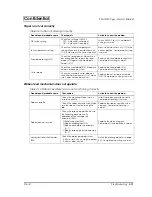
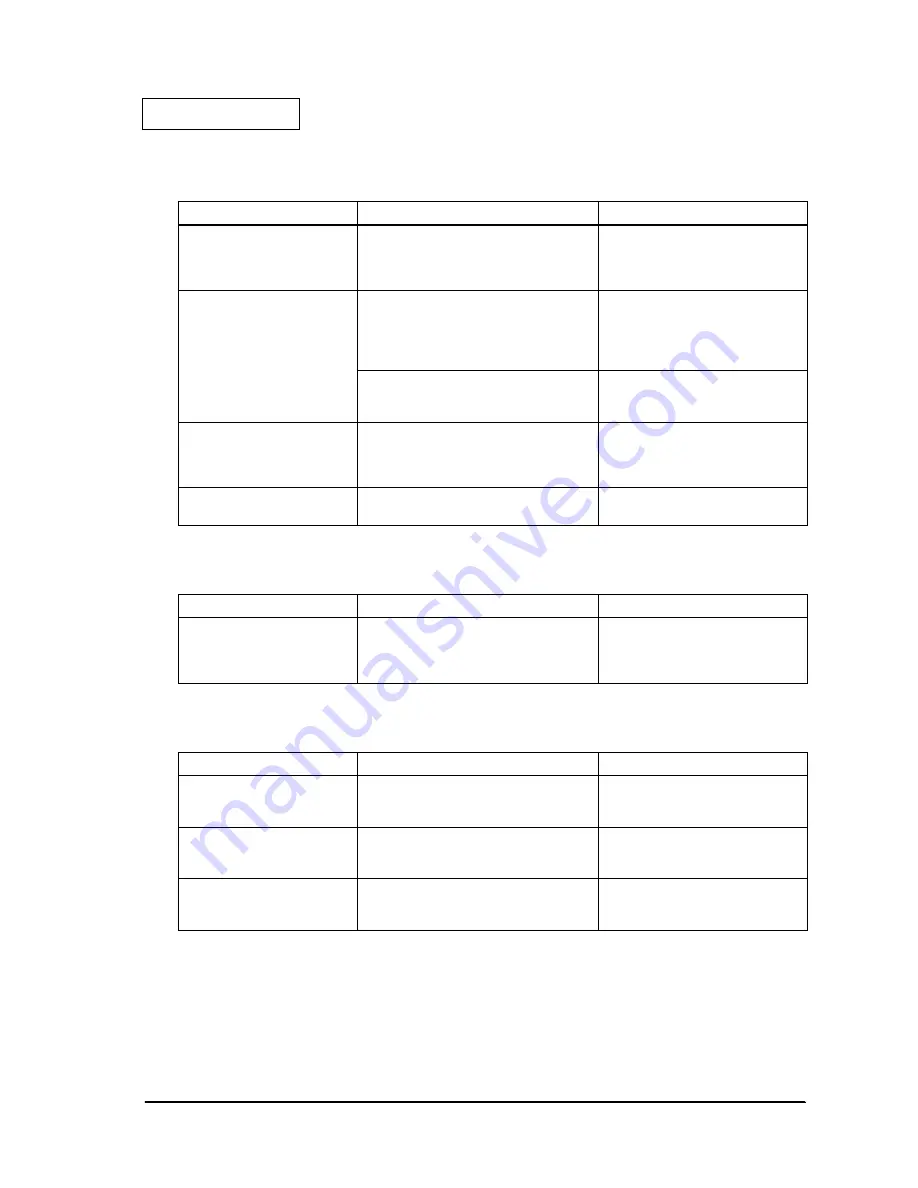
Cannot pass the test for the roil cover
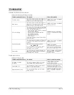
Cannot pass the test for the paper FEED button
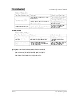
Cannot pass the test for drawer 3 status
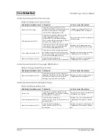
Table 3-24 Paper Roll Cover Test Fails
Probable part/probable cause
Checkpoints
Action to correct the problem
Memory switch setting
Check the setting of MSW 8-5. If the
setting is OFF, status is not sent from the roll
cover, but the RE sensor is changed.
Confirm if the setting status is ON.
Change the setting of MSW 8-5 to
ON. Completed if the test passes.
HP board assembly (518)
Check the connection. Make sure the
cable is plugged in. Make sure the
connector on the HP board assembly
(518) is connected to connector (CN4) on
the main circuit board unit (201).
Plug in the connector. Completed if
the test passes.
Check the continuity with a tester. Make
sure wires are not cut or shorted out. Be
sure wires are arranged correctly.
Replace the HP board assembly
(518). Completed if the test passes.
Cover open assembly (515)
Check the continuity of the wires for the
cover open assembly (515) with a tester.
Be sure wires are not cut or shorted out. Be
sure wires are arranged correctly.
Replace the cover open assembly.
Completed if the test passes.
Main circuit board unit (201)
Check the parts for defects.
Make sure connector (CN4) is connected.
Replace the main circuit board unit.
Completed if the test passes.
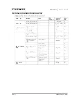
Table 3-25 Paper FEED Button Test Fails
Probable part/probable cause
Checkpoints
Action to correct the problem
Main circuit board unit (201)
Check the operation of SW2. Make sure
roll paper is fed when you press the paper
FEED button. Make sure the continuity
changes when you press the button.
Replace the main circuit board unit.
Completed if the test passes.
Table 3-26 Drawer 3 Status Fails
Probable part/probable cause
Checkpoints
Action to correct the problem
Drawer kick
Check the connection. Make sure the
cable is plugged in. Check each leading
pin for drawer 1 or drawer 2.
Plug in the connector. Completed if
the drawer is kicked out.
Sub circuit board unit (123)
Check the parts for defects.
Make sure connectors (CNC2 and CNC3)
are connected.
Replace the sub circuit board unit.
Completed if the drawer is kicked
out.
Main circuit board unit (201)
Check the parts for defects.
Make sure connector (CN10) is
connected.
Replace the main circuit board unit.
Completed if the drawer is kicked
out.


