SIC63616-(Rev. 1.0) NO. P157
3240-0412
D3
D2
D1
D0
Name Init
∗
1
1
0
TC15
TC14
TC13
TC12
–
∗
2
–
∗
2
–
∗
2
–
∗
2
R/W
FF6AH
TC15
TC14
TC13
TC12
TC19
TC18
TC17
TC16
–
∗
2
–
∗
2
–
∗
2
–
∗
2
R/W
FF6BH
TC19
TC18
TC17
TC16
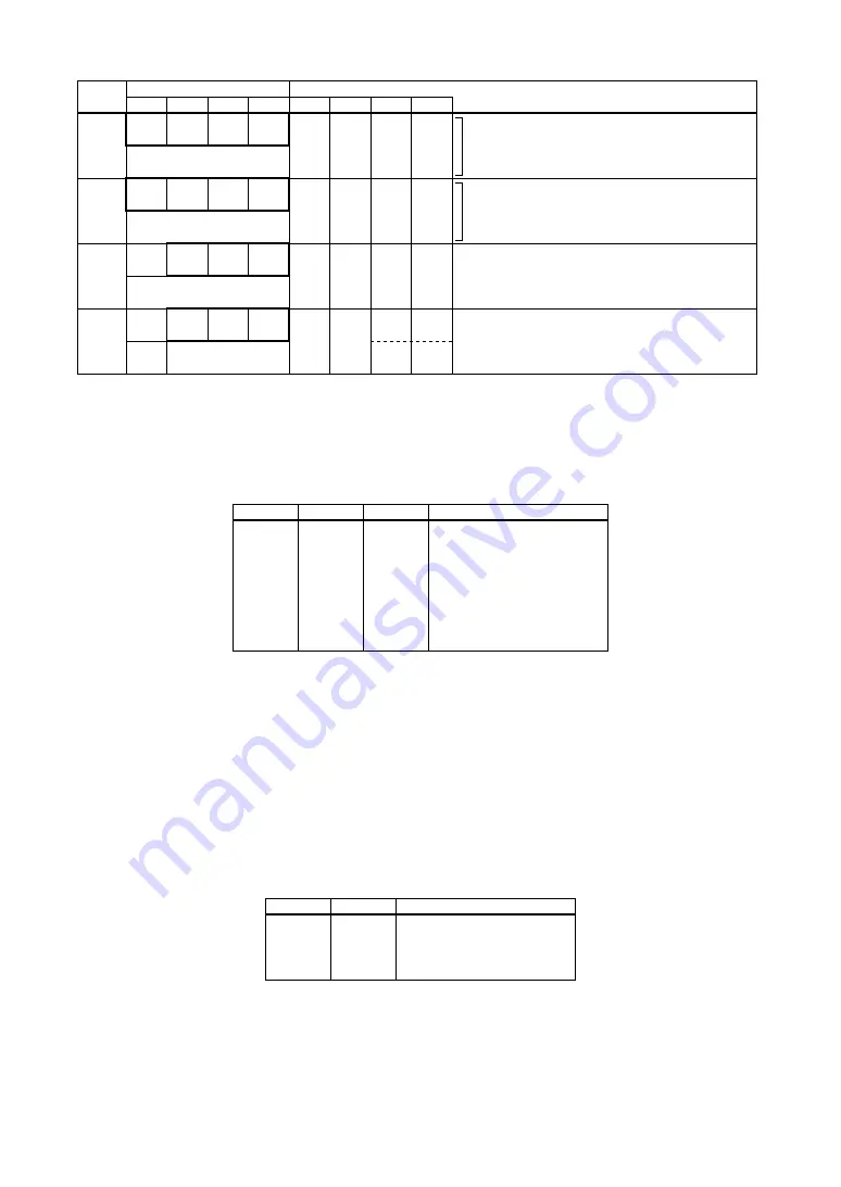
Time base counter TC12–TC15
MSB
Time base counter TC16–TC19
Address
Comment
Register
FFE1H
General EIRFE EIRFR EIRFS
R/W
General
EIRFE
EIRFR
EIRFS
0
0
0
0
1
Enable
Enable
Enable
0
Mask
Mask
Mask
General-purpose register
Interrupt mask register (R/f converter error)
Interrupt mask register (R/f converter reference oscillate completion)
Interrupt mask register (R/f converter sensor oscillate completion)
Unused
Interrupt factor flag (R/f converter error)
Interrupt factor flag (R/f converter reference oscillate completion)
Interrupt factor flag (R/f converter sensor oscillate completion)
FFF1H
0
IRFE
IRFR
IRFS
R/W
0
∗
3
IRFE
IRFR
IRFS
–
∗
2
0
0
0
(R)
Yes
(W)
Reset
(R)
No
(W)
Invalid
R
*1 Initial value at initial reset
*3 Constantly "0" when being read
*2 Not set in the circuit
RFCKS0–RFCKS2: R/f converter clock frequency select register (FF15H•D0–D2)
Selects the R/f converter clock frequency.
Table 4.13.7.2 R/f converter clock frequencies
RFCKS2
1
1
1
1
0
0
0
0
RFCKS1
1
1
0
0
1
1
0
0
RFCKS0
1
0
1
0
1
0
1
0
R/f converter clock
f
OSC3
/ 4
f
OSC3
/ 2
f
OSC3
/ 1
Programmable timer 1
f
OSC1
/ 4 (8 kHz)
f
OSC1
/ 2 (16 kHz)
f
OSC1
/ 1 (32 kHz)
Off
f
OSC1
: OSC1 oscillation frequency. ( ) indicates the frequency when f
OSC1
= 32 kHz.
f
OSC3
: OSC3 oscillation frequency
When programmable timer 1 is selected, the programmable timer 1 underflow signal is divided by 2 before it
is used as the R/f converter clock. In this case, the programmable timer must be controlled before operating
the serial interface. Refer to Section 4.8, "Programmable Timer" for controlling the programmable timer.
If it is not necessary to run the R/f converter, stop the clock supply by setting this register to "000B" to
reduce current consumption.
At initial reset, this register is set to "000B".
ERF0, ERF1: R/f conversion select register (FF60H•D0–D1)
Selects the channel and sensor type to perform R/f conversion.
Table 4.13.7.3 Selecting channel and sensor type
ERF1
1
1
0
0
ERF0
1
0
1
0
Channel and sensor type
Ch.1 DC
Ch.1 AC
Ch.0 DC
I/O
DC: R/f conversion using a DC bias resistive sensor such as a thermistor
AC: R/f conversion using an AC bias resistive sensor such as a humidity sensor
The R/f converter channel 0 input/output terminals are shared with the I/O port (P00–P02). By setting
this register to other than "00B", P00, P01 and P02 are configured as the RFIN0, REF0 and SEN0 terminals,
respectively.
At initial reset, this register is set to "00B".
Содержание S1C63616
Страница 1: ...S1C63616 Technical Manual Rev 1 0 ...


