M200 / M205 / M100 / M105 Series
Revision A
Disassembly/Reassembly
Detailed Disassembly/Reassembly Procedure for each Part/Unit
53
Confidential
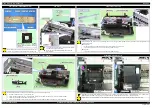
Tube Guide Sheet / Tube Guide Sheet Sub
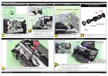
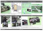
Refer the figure above and follow the procedure below when attaching the Tube Guide Sheet Sub to the Tube Guide Sheet.
1. Insert the section A of the Tube Guide Sheet Sub into the hole 1 of the Tube Guide Sheet from the top.
2. Insert the section A of the Tube Guide Sheet Sub into the hole 2 of the Tube Guide Sheet from the bottom.
When attaching the Tube Guide Sheet to the Ink Supply Tube Guide 2nd, while keeping the Tube Guide Sheet Sub attached on the Tube Guide
Sheet, align the holes of the Tube Guide Sheet with the protrusions of the Ink Supply Tube Guide 2nd.
OK
Cross Section
NG
Hole 2
Tube Guide Sheet Sub
Tube Guide Sheet
Tube Guide Sheet
Hole 1
Hole 2
Section A
Hole 1
Tube Guide Sheet
Tube Guide Sheet Sub
Tube Guide Sheet
Tube Guide Sheet Sub
Ink Supply Tube Guide 2nd
Housing Ink Supply Tank
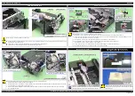
Be careful about how to place the Ink Supply Tank Assy in order to prevent printing failure from occurring. (See
ASSY WHEN DISASSEMBLING/REASSEMBLING (p26)"
Install the Housing Ink Supply Tank as follows.
1. Align the two positioning holes on the Ink Supply Tank with the two dowels on the Housing Ink Supply Tank, then attach the Ink Supply Tank to
the Housing Ink SupplyTank.
2. Insert the lever section of the Valve Assy into the hole on the Housing Ink Supply Tank, and align the two positioning holes on the Valve Assy
with the two dowels on the Housing Ink Supply Tank, then attach the Valve Assy to the Housing Ink Supply Tank.
3. Secure the Ink Supply Tank and Valve Assy to the Housing Ink Supply Tank with the three screws.
Lever section
Hole
Ink Supply Tank
Housing Ink Supply Tank
Housing Ink Supply Tank
C.B.P-TITE SCREW 3x6 F/ZN-3C (6 ± 1 kgf·cm)
Dowel
Positioning hole
Ink Supply Tank
Valve Assy
Ink Supply Tube
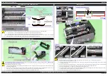
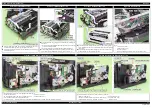
Install the Ink Supply Tube as follows.
1. Mark the position 72
±
1 mm away from the adapter of the Ink Supply Tube and 158.4
±
1 mm away from the joint of the tube.
2. Connect the Ink Supply Tube with the joint.
3. Using the marking based on the joint of the Ink Supply Tube as the reference, attach the Tube Clamp to the Ink Supply Tube with the C cut of the
Tube Clamp facing upward.
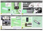
4. Place the Ink Supply Tube on the Tube Guide Sheet, and insert the section A of the Tube Guide Sheet Sub into its hole on the other side from the
bottom to secure them. Make sure that the Tube Clamp is attached within the inside of the Tube Guide Sheet Sub.
5. Connect the Ink Supply Tube to the adapter, and attach the adapter to the CR Unit.
6. Insert the Ink Supply Tube into the groove on the CR Unit and align the marking on the Ink Supply Tube with the edge of the CR Unit. Make
sure that the red line on the Ink Supply Tube faces the front of the printer.
7. Attach the Tube Pressing Plate and secure it with the two screws.
72
±
1 mm
158.4
±
1 mm
Joint side
Adapter side
Ink Supply Tube (Bottom side): Step 1
Markings
Tube Clamp
Adapter
Ink Supply Tube
Align markings with
edge of grooves.
CR Unit
Grooves
Step 6
CR Unit
Joint
Tube Pressing Plate
Ink Supply Tube
Step 7
Step 3, 4
C.B.P-TITE SCREW 2.6x5 F/ZN-3C (6 ± 1 kg·fcm)
OK
Ink Supply
Tube
Section A
Hole
Tube Guide
Sheet Sub
NG
Ink Supply
Tube
Section A
Hole
Tube Guide
Sheet Sub
Tube Guide Sheet Sub
Tube Clamp
C cut
Содержание M200
Страница 1: ...SERVICE MANUAL CONFIDENTIAL Color Inkjet Printer M200 M201 M205 M100 M101 M105 SEMF12 012 ...
Страница 6: ...Confidential Revision Status Revision Date of Issue Description A October 17 2012 First Release ...
Страница 9: ...Confidential CHAPTER 1 TROUBLESHOOTING ...
Страница 18: ...Confidential CHAPTER 2 DISASSEMBLY REASSEMBLY ...
Страница 59: ...Confidential CHAPTER 3 ADJUSTMENT ...
Страница 73: ...Confidential CHAPTER 4 MAINTENANCE ...
Страница 80: ...Confidential CHAPTER 5 APPENDIX ...

