


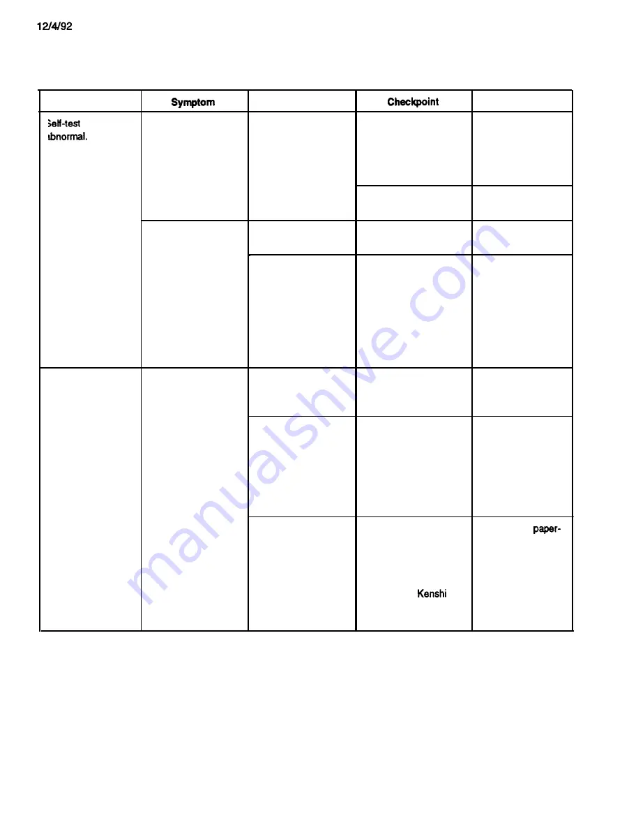
Table 5-6. Repair of the Printer Mechanism (Cont.)
Problem
Cause
Solution
printing is
A particular dot fails
to print.
The printhead is
defective.
Measure the coil
resistance of the
printhead. The normal
value is approximately
16.7 ohms.
Replace the
printhead.
Check whether the dot
Replace the
wire is worn.
printhead.
The printing is too
The printhead is
Check whether the tip
Replace the
light, or the print
defective.
of the dot wire is worn.
printhead.
density is not uniform.
The platen gap is not
Set the gap adjust lever
Adjust the gap.
properly adjusted.
to the second position,
Refer to Section
and check the gap
4.1.2,
Platen Gap
between the tip of the
Adjustment.
printhead and the
platen.
The appropriate value is
0.38
mm.
Paper feeding is
abnormal.
Printing is performed,
but the paper is not
fed, or is not fed
uniformly.
A foreign substance
Perform a visual check
Remove any foreign
is lodged in the paper
of the paper path.
substance.
path.
The paper-feed motor
Check that no foreign
l
Remove any
is not driving the gear
substance is lodged
foreign substance.
correctly.
between the gears, and
l
Replace the
that the gears are not
paper-feed
broken or worn.
reduction gear.
l
Replace the platen
gear.
The paper-feed motor
Measure the coil
Replace the
is defective.
resistance for the
feed motor.
paper-feed motor.
The approximate value
should be 56 ohms (for
the Shinano
motor) or 51 ohms (for
the Seiko Epson motor).
5-20
Содержание LQ-1170
Страница 1: ...LQ 1170 24 PIN DOT MATRIX PRINTERS TM LQ8 1170 ...
Страница 2: ...L Q 8 7 0 1 1 7 0 SERVICE MANUAL EPSON T Printed on recycled paper ...
Страница 6: ...Revision Level Revision Date I 1st printing I 7 23 91 I I ViSC d I 10 g 91 I 1 2ndprhting I 3 17 92 I ...
Страница 20: ...REV A Table 1 9 Printing Bit Image Mode 80 136 Column dpi dots per inch ips inches per second 1 11 ...
Страница 101: ...10 9 91 Yes NO Replace pluggable chips on main board 5 6 ...
Страница 110: ...Table 5 4 Repair of the Power Supply Board Continued 5 15 ...
Страница 118: ......
Страница 121: ...REV A Figure 6 2 LQ 870 Lubrication Points 6 3 ...
Страница 122: ...REV A Figure 6 3 LQ 1170 Lubrication Points 6 4 ...
Страница 134: ...1 I II ...
Страница 135: ...REV A Q m u D w IL 0 1 xl Figure A 3 CO60 DRV Board Circuit Diagram A 11 ...
Страница 136: ...Figure A 4 CO60 PSB Board Circuit Diagram A 12 ...
Страница 138: ...LO SLOE002 OWO9 1Nd 0 9 0 3 5 f l P I 11 I 01 I 6 I 8 1 L 9 I 9 I B I I2 I 2 I 1 ...
Страница 141: ...REV A s XL r t RI FI IZSV SA 0 l Dl I N 0 I I D E C6 I I U J Figure A 9 CO60 PSB Board Component Layout A 1 7 ...
Страница 142: ...REV A Fl 24ov T3 IsA I I II II AL I CU rl Figure A 10 C060 PSE Board Component Layout A 1 8 ...
Страница 143: ...LMS d10 IP IMS dla ...
Страница 144: ...REV A A 4 EXPLODED DIAGRAM Figure A l 2 1 Exploded Diagram for LQ 870 A 2 0 ...
Страница 145: ......
Страница 146: ...REV A Figure A 13 1 Exploded Diagram for Model 5DlO A 22 ...
Страница 147: ... 5 2 5 610 c 3 5 9 0 El ...
Страница 149: ...REV A A 5 CASE OUTLINE DRAWING Figure A l 4 1 Case Outline Drawing for LQ 870 A 25 ...
Страница 150: ...REV A 7 _ I i I 11111 j I I g I I II I I Figure A l 4 2 Case Outline Drawing for LQ 1170 A 2 6 ...
Страница 151: ...lllllll IllI l l IIIIII II0 IIll III1 I I I C O 6 1 M A I N B o a r d A 3 7 ...
Страница 152: ... U nRonenl2 i i C O 6 0 HAIN B t _1 m r OL J IIA IS I 19 CNI 36 I I8 I 23 IS ...
Страница 153: ...a i iJ 0 E fig tfti I z ...