Rev. A
Assembly and Disassembly 6-55
EU-T432 Technical Manual
Confidential
4
C.B (3
××××
4)
×
4
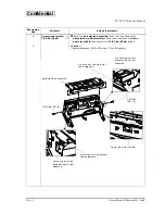
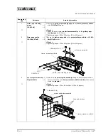
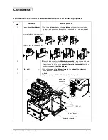
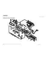
Control circuit board
module
×
1
❏
Connect the cable head
cable head
cable head
cable head and the cable, printer
cable, printer
cable, printer
cable, printer of the printer module to
the connectors on the
control circuit board module
❏
Pass the
lead wire, NE detector
between the
cover, circuit board lower
and the
control circuit board module
; then secure the
control circuit
board module
to the
cover, circuit board lower
with
C.B (3
××××
4)
screws.
★
< Check >
❏
Tightening torque: 735 to 931 mN
•
m {7.5 to 9.5 kg
•
cm}
❏
When securing the
control circuit board module
, slightly push it downward.
Pass the hooks of the parallel interface through the hole on the
circuit
board, lower
.
5
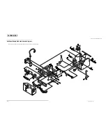
LED switch circuit board
assembly
×
1
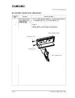
C.B (M3
××××
4)
×
2
❏
Secure the
LED switch circuit board assembly
with
C.B (M3
××××
4)
screws.
★
< Check >
❏
Tightening torque: 735 to 931 mN
•
m {7.5 to 9.5 kg
•
cm}
6
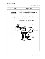
H. nut (2.6)
×
2
❏
Secure the serial connector to the
cover, circuit board lower
with
H. nuts
.
★
< Check >
❏
Tightening torque: 392 to 588 mN
•
m {4.0 to 6.0 kg
•
cm}
Reassembly
step
Part name
Assembly procedure
C.B (3
×
4)
LED switch circuit board assembly
C.B (3
×
4)
H. nut
hook
Содержание EU-T432
Страница 1: ...Confidential Technical manual Thermal printer unit EU T432 English 4013753 Issued Date 200 Issued by ...
Страница 122: ...Rev A Appendix 5 EU T432 Technical Manual Confidential EU T432 Lubrication Diagram 13 G 36 13 G 36 ...
Страница 124: ...Rev A Appendix 7 EU T432 Technical Manual Confidential Cut Sheet Presenter Module Lubrication Diagram 14 G 36 ...
Страница 126: ...SEIKO EPSON CORPORATION Printed in Japan ...

