3.2.3 Disassembling the Engine
This section describes disassembling the engine, including the high voltage unit (PWB-F) and
power supply board (PWB-E).
3.2.3.1 Optical Unit Removal
CAUTION
❒
Do not touch the optical unit except at the time of replacement.
❒
Do not open the unit under any conditions.
❒
Do not remove the circuit board from the optical unit under any conditions.
1.
Open the top cover.
2.
Remove the right cover, left cover, and front cover. (Refer to Section 3.2.1.1.)
3.
Remove the cover shield plate.
4.
Disconnect connector CN205 and CN210 from the C169 MAIN Board.
4.
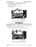
Remove the 6 screws (#4) from the optical unit.
5.
Remove the optical unit.
Figure 3-4. Removing the Optical Unit
Disassembly and Assembly
EPL-5500 Service Manual
3-6
Rev. B
Содержание EPL-5500
Страница 1: ...EPSON TERMINAL PRINTER EPL 5500 SERVICE MANUAL EPSON 4005431 ...
Страница 2: ... ii ...
Страница 12: ...Rev A 1 iii ...
Страница 62: ...EPL 5500 Service Manual Operating Principles Rev B 2 11 ...
Страница 122: ...6 ii Rev A ...
Страница 125: ...EPL 5500 Service Manual Maintenance Rev B 6 3 ...
Страница 142: ...Figure A 8 C169 MAIN B Component Layout Rear EPL 5500 Service Manual Appendix Rev A A 17 ...
Страница 144: ......
Страница 145: ...EPSON ...


