2.2.1.5 Parallel Interface Circuit
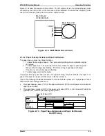
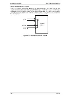
Figure 2-31 shows a circuit block diagram of the parallel interface. Data sent from the host
computer is latched within the E05A93 by the STROBE signal. The E05A93 outputs a BUSY signal
automatically to stop the host computer from sending additional data. The CPU resets the BUSY
signal after reading the data from the E05A93, so that the printer is ready to receive more data from
the host computer.
Latch
STROBE
BUSY
DATA
E05A93
(IC4)
Figure 2-31. Parallel Interface Circuit
Operating Principles
EPL-5500 Service Manual
2-22
Rev. B
Содержание EPL-5500
Страница 1: ...EPSON TERMINAL PRINTER EPL 5500 SERVICE MANUAL EPSON 4005431 ...
Страница 2: ... ii ...
Страница 12: ...Rev A 1 iii ...
Страница 62: ...EPL 5500 Service Manual Operating Principles Rev B 2 11 ...
Страница 122: ...6 ii Rev A ...
Страница 125: ...EPL 5500 Service Manual Maintenance Rev B 6 3 ...
Страница 142: ...Figure A 8 C169 MAIN B Component Layout Rear EPL 5500 Service Manual Appendix Rev A A 17 ...
Страница 144: ......
Страница 145: ...EPSON ...


