background image

Installation Guide

25

Aspect ratio for standard projected image

When installing the Touch Unit

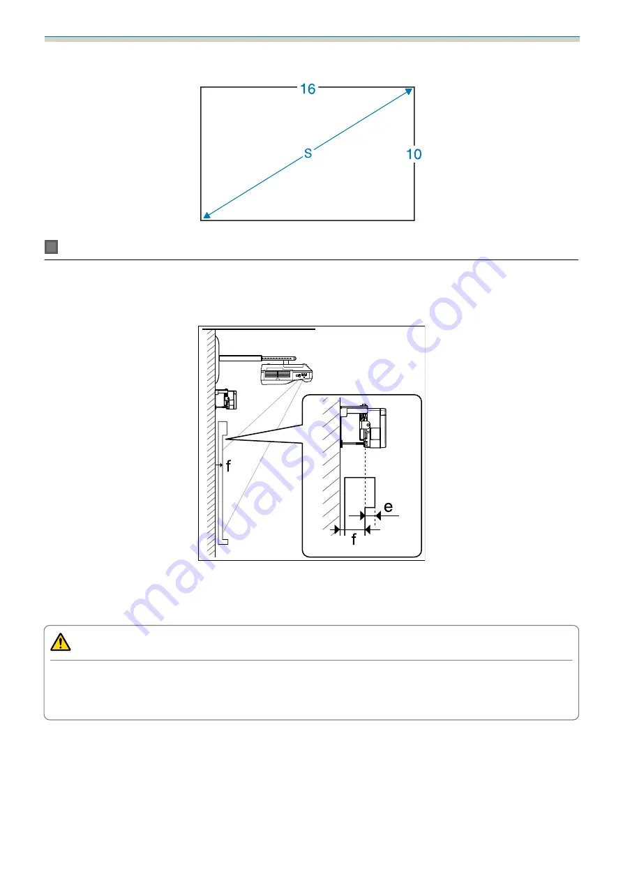
By using the supplied Touch Unit Bracket, you can install the Touch Unit outside the whiteboard.

When installing the Touch Unit outside the whiteboard, measure the length from the surface where the Touch
Unit is installed to the whiteboard surface ((f) in the following figure).

When (f) is 20 to 50 mm, you can install the Touch Unit outside the whiteboard using the bracket.

When (f) is less than 20 mm or more than 50 mm install the Touch Unit on the whiteboard.

When the thickness of the top of the frame (e) is 3 mm or more, install the Touch Unit on the whiteboard.

Caution

Install the bottom edge of the Touch Unit so that it is 25 to 100 mm from the top edge of the projected image.

If there are obstacles between the projected image and the Touch Unit such as cables, whiteboard trays,
or holders, the Touch Unit will not operate correctly.

Содержание EB-1470Ui

Страница 1: ...Installation Guide ...

Страница 2: ...ling Caution This symbol indicates information that if ignored could possibly result in personal injury or physical damage due to incorrect handling Explanation of Symbols Symbols Explanation Symbol indicating an action that must not be done Symbol indicating an action that should be done c Symbol indicating related or useful information Safety Precautions for Installation Warning The setting plat...

Страница 3: ...of the pro jector and the setting plate is approximately 20 kg not including cables Ensure the strength of the wall before mounting this product on the wall If the wall is not strong enough reinforce the wall before installation Inspect the setting plate on a regular basis to ensure there are no broken parts or loose screws If any parts are damaged stop using the setting plate immediately If this ...

Страница 4: ...e and cause a fire Avoid locations subject to high temperatures such as close to heaters and leave a gap of at least 50 cm between the wall and the air exhaust vent Do not use the projector in a location subject to combustible or explosive gas The projector may catch fire because of the high temperature inside the projector If any abnormalities occur with this product immediately disconnect the ca...

Страница 5: ...high power laser product that could cause a fire electric shock or an accident Only connect the Touch Unit to the EB 1470Ui Do not connect it to any other projectors or devices The device could malfunction or laser light that is higher than normal intensity could be emitted Do not go near the Touch Unit if you are using medical equipment such as a pace maker Furthermore when using the Touch Unit m...

Страница 6: ...Using the Product Safely 5 It also describes how to install the Touch Unit Control Pad and Pen Stand after mounting the projector on a wall ...

Страница 7: ...y overheat and the power may turn off without warning When using the projector in an environment of 35 C or more install a partition to block the heat vented from the projector s air exhaust vent Make sure the partition is slightly larger than the exhaust vent approx 2 cm wider and taller and then install the partition 30 cm from the exhaust vent It is recommended to keep connection cable length l...

Страница 8: ...een Install vertically on a table and project from the front of the desk When installing vertically on a table you need the optional Interactive Table Mount ELPMB29 Before installing the Touch Unit make sure that the installation surface is not warped or distorted and that any unevenness on the screen surface is less than 5 mm When installing the Touch Unit on a whiteboard secure the Touch Unit wi...

Страница 9: ... f is more than 50 mm you cannot install the Touch Unit outside the whiteboard If there is a frame around the screen make sure that the thickness of the top of the frame e is less than 3 mm If the thickness of the top of the screen exceeds 3 mm the Touch Unit will not operate correctly ...

Страница 10: ...d labels 22 Laser diffusion port 23 Projection Distance Table 24 Figures of Installation Dimensions 24 When installing the Touch Unit 25 When installing the Control Pad and the Pen Stand 28 WhenProjectedImageisSmallerthan85Inches 29 16 10 projected image 30 When Projected Image is 85 inches or more 31 16 10 projected image 32 Installing the Setting Plate 33 Connecting Devices 33 Necessary cables 3...

Страница 11: ...lti Projection 99 When two projectors are installed in parallel and you are using the interactive function 100 Setting the projectors in sync 100 Setting Multi Projection Interactive 102 Batch Setup Function 109 Setup Using a USB flash drive 110 Saving settings to the USB flash drive 110 Copying saved settings to other projectors 112 When Setup Fails 112 Attaching a Security Cable 114 ...

Страница 12: ...eractive Pen s p 55 d Installing the Control Pad and the Pen Stand s p 62 When installing the Touch Unit finish installing the projector first and then follow the procedures below The procedure differs depending on where the Touch Unit is to be installed When installing the Touch Unit outside the whiteboard using the Touch Unit Bracket a Installing the Touch Unit s p 65 b Adjusting the Angle of La...

Страница 13: ...when multiple projectors are installed in parallel to project one large screen follow the steps below a Installing the Setting Plate and the Projector s p 33 b Adjusting the Position of the Projector s p 46 c Setting the Projector ID s p 96 d Adjusting the Image in Multi Projection s p 99 When twoprojectorsare installedin parallel andyouwant tousetheinteractivefunction makethefollowing settings Ma...

Страница 14: ...ner 13 mm for M8 and M6 6 mm for hexagonal axis Shape Name Quan tity Application M4x12mmhexagonsocketheadcapbolt with washer spring washer 5 For wall plate assembly 4 For 3 axis adjustment unit arm installation 4 For slide plate projector installation M6 x 20 mm hexagon shoulder head bolt with washer spring washer 1 For setting plate wall plate installation M6 x 20 mm cross recessed head shoulder ...

Страница 15: ...all items before beginning Control Pad Pen Stand Stereo mini cable for connecting the Control Pad approx 5m Port protection stickers When installing the Control Pad on a wall and so on prepare commercially available M4 screws 20 mm x4 When installing the Pen Stand on a wall and so on prepare commercially available M4 screws 20 mm x2 ...

Страница 16: ...5 cm x8 Spacer for screw hole x3 Label x4 Tape for securing the markers approx 6 cm x12 When installing the Touch Unit on a non magnetic whiteboard prepare three commercially available M4 screws Touch Unit Bracket Installation plate Securing plate M4 x 10 mm hexagon socket head cap bolts x2 M4 x 25 mm hexagon socket head cap bolts x2 M4 x 55 mm hexagon socket head cap bolt x1 M4 x 70 mm hexagon so...

Страница 17: ...e fig ure below Horizontal roll adjustment range 3 Fine adjustments possible with adjust ment dial s p 46 Horizontal rotation adjustment range 8 Fine adjustments possible with adjust ment dial s p 46 Vertical tilt adjustment range 3 Fine adjustments possible with adjust ment dial s p 46 Horizontal slide adjustment range 45 mm See the fig ure below Wall plate cover The following dimensions apply wh...

Страница 18: ... 24 24 131 131 99 99 79 192 3 234 4 24 60 24 496 5 1 5 1 R 1 0 The offset value for the position of the center of the projected image and the center of the wall plate is 27 mm Cable routing holes Whenroutingcablestoconnecttotheprojectorthroughawall usepositions and inthefollowing figure as the cable routing holes Vertical slide adjustment range Unit mm ...

Страница 19: ...ent range Arm slide adjustment range Unit mm Adjustment range for 3 axis adjustment unit installation position Unit mm Position for installing accessories These screw holes allow you to secure peripheral devices and accessories such as external tuners Use commercially available M4 screws Unit mm ...

Страница 20: ...35 Control Pad Pen Stand Control Pad external dimensions weight Unit mm 140 178 34 5 30 5 60 16 6 51 5 63 3 50 1 109 15 5 4 x M4 Weight approx 262 g Operating temperature 0 to 50 C no condensation Operating temperature 20 to 60 C no condensation ...

Страница 21: ...ollowingfigure as the cable routing hole Otherwise remove the cable cover and route the cables from there Route the printer cable along the groove at the back of the Control Pad Pen Stand external dimensions weight Unit mm 99 9 70 0 101 9 44 4 28 8 28 8 35 5 36 0 2 x M4 The Pen Stand weighs approximately 93 g ...

Страница 22: ...e 21 Touch Unit Touch Unit external dimensions weight Unit mm The Touch Unit weighs approximately 450 g Touch Unit Bracket external dimensions adjustment range weight Top Unit mm 229 8 228 57 62 Front Unit mm 101 104 8 ...

Страница 23: ...oximately 750 g Attached labels The Touch Unit is a Class 1 laser product that conforms to the IEC EN60825 1 2014 standard There are warning labels affixed to the Touch Unit to indicate that it is a Class 1 laser product The labels contain the following information Class 1 laser product Warning Do not open the case The device contains a high power laser product Warning ...

Страница 24: ...ss 3B invisible laser radiation will be emitted Avoid exposure to the radiation beams Laser diffusion port The laser beam is diffused from the laser diffusion ports at the back of the Touch Unit Light source output power Maximum 285 mW x 2 Wavelength 932 960 nm ...

Страница 25: ...osition ofthecenter oftheprojected imageand the centerof thewallplateis27mm Unit mm Projected image size Wall plate Minimum projection distance Wide maxi mum zoom to maximum Tele minimum zoom Screen Numbers on the arm slide scale Distance from the top of the projected image to the bottom wall plate installation screw hole Distance from the top of the projected image to the wall plate temporary sec...

Страница 26: ...ing figure When f is 20 to 50 mm you can install the Touch Unit outside the whiteboard using the bracket When f is less than 20 mm or more than 50 mm install the Touch Unit on the whiteboard When the thickness of the top of the frame e is 3 mm or more install the Touch Unit on the whiteboard Caution InstallthebottomedgeoftheTouchUnitsothatitis25to100mmfromthetopedgeoftheprojectedimage If there are...

Страница 27: ...y obstacles such as a frame or tray at the bottom of the screen touch operations will not operate correctly Stick the supplied infrared deflectors along the locations of the obstacles s p 52 Make sure there is a space of approximately 20 mm between the place where the infrared deflector is stuck and the bottom of the projected image ...

Страница 28: ...s a frame or tray at the bottom of the screen touch operations will not operate correctly Stick the supplied infrared deflectors over the locations of the obstacles s p 52 Make sure there is a space of at least 20 mm between the place where the infrared deflector is stuck and the bottom of the projected image If there are obstacles in the shaded areas in the following figure such as cables whitebo...

Страница 29: ... in the following figure Unit mm 㻝㻜㻜 㻡㻜 㻝㻜㻜 㻝㻜㻜 When installing the Pen Stand next to the Control Pad do not install it so that it covers the groove in the front cover as shown in the following figure c When installing the Touch Unit do not install the Control Pad on the projection screen and the surrouding area shaded area in the following figure Otherwise The Touch Unit will not operate correctl...

Страница 30: ...table provides the figures when mounting the 3 axis adjustment unit at the position marked with a stamp The distance from the top of the projected image to the bottom wall plate installation screw hole c is the number given when the vertical slide is set to the standard position Match the notch on the setting plate to the position of the stamp on the wall plate ...

Страница 31: ...7 75 161 5x101 0 8 7 to 25 2 19 6 to 36 1 25 1 44 3 101 0 76 163 7x10² 3 9 3 to 26 0 20 2 to 36 9 25 4 44 6 102 3 77 165 9x10³ 7 10 0 to 26 9 20 9 to 37 8 25 7 44 9 103 6 78 168 0x105 0 10 6 to 27 7 21 5 to 38 6 26 0 45 2 105 0 79 170 2x10⁶ 3 11 2 to 28 6 22 1 to 39 5 26 2 45 4 106 4 80 172 3x10⁷ 7 11 8 to 29 4 22 7 to 40 3 26 5 45 7 107 7 81 174 5x10⁹ 0 12 5 to 30 3 23 4 to 41 2 26 8 46 0 109 0 8...

Страница 32: ...ble provides the figures when mounting the 3 axis adjustment unit at the position marked with a stamp The distance from the top of the projected image to the bottom wall plate installation screw hole c is the number given when the vertical slide is set to the standard position Match the notch on the setting plate to the position of the stamp on the wall plate ...

Страница 33: ...o 37 9 20 3 to 40 1 29 3 48 5 121 2 91 196 0x122 5 18 7 to 38 7 20 9 to 40 9 29 6 48 8 122 5 92 198 2x123 9 19 4 to 39 6 21 6 to 41 8 29 9 49 1 123 8 93 200 3x125 2 20 0 to 40 4 22 2 to 42 6 30 2 49 4 125 2 94 202 5x126 5 20 6 to 41 3 22 8 to 43 5 30 5 49 7 126 5 95 204 6x127 9 21 3 to 42 1 23 5 to 44 3 30 7 49 9 127 9 96 206 8x129 2 21 9 to 43 0 24 1 to 45 2 31 0 50 2 129 2 97 208 9x130 6 22 5 to...

Страница 34: ...ied Touch Unit connection cable supplied Stereo mini cable supplied Other cables prepare according to the connected devices For details see the projector s User s Guide on the Document CD ROM Necessary cables when using the Easy Interactive Function When performing mouse operations using the Easy Interactive Function you need a USB cable Even when projecting using a computer cable a USB cable is n...

Страница 35: ...interactive function connect a USB cable from the computer to each projector You need a computer with two USB A ports Necessary cables when installing the Touch Unit You need the supplied Touch Unit connection cable when installing the Touch Unit and connecting it to the projector Operations are not performed correctly with a commercially available cable The shape of the plug that connects to the ...

Страница 36: ... the USB storage device you need the USB cable supplied and a commercially available USB storage device When printing the projected image you need the USB cable supplied and the USB cable supplied with your printer When inputingcharacters with a USB keyboardusingtheRemoteDesktopfunction you need the USB cable supplied and a commercially available USB keyboard c The following Epson projectors can b...

Страница 37: ...o not use adhesives lubricants or oils to install or adjust the setting plate If you use adhesives to prevent the screws from loosening or things such as lubricants or oils on the slide plate fixing part of the projector the case may crack and cause the projector to fall resulting in personal injury or property damage Assemble the parts a Connect the plate and frames x2 and secure with the M4 x 12...

Страница 38: ...n If the standard position is not correct loosen the M4 bolt and adjust the position of the slide plate When you have finished making adjustments tighten the bolt c Secure the 3 axis adjustment unit and the slide plate to the base of the projector with the M4 x 12 mm bolts x4 supplied Bolt installation positions ...

Страница 39: ...ected image to the wall plate temporary securing screw hole d s Projection Distance Table p 24 c Use the screw hole in the following figure as the temporary screw hole for the wall plate The distance from the bottom wall plate installation screw hole to the temporary screw hole is 192 3 mm We recommend marking the following positions These willbe the basis for determining the mounting position of ...

Страница 40: ... right from the center line of the projection surface up to a maximum of 45 mm Match the height and checked in step 1 to the lines on the template sheet Unit mm c Drive a commercially available M10 screw into the position of the temporary screw hole for the wall plate Leave a gap of 6 mm or more between the wall and the screw head d Determine the positions for the mounting holes for the wall plate...

Страница 41: ...mercially available anchors into the holes Attach the nut and tap it with a hammer until the core touches the top of the an chor h Tighten the nut with a commercially available spanner to secure the wall plate to the wall Determine the projection distance and then pass the cables through the setting plate a Check the following values in the projection distance table Numbers on the arm slide scale ...

Страница 42: ...to route the cables so that the ends of the cables that connect to the projector are on the projector s interface side Warning Do not hang the rest of the cable over the setting plate They could fall and cause an accident c Route the Touch Unit connection cable through the setting plate Route the cable so that the end that connects to the Touch Unit appears from the lower part of the setting plate...

Страница 43: ... plate to the wall plate Insert the top of the hexagonal axis into the wall plate and then insert it into the slot at the bottom Caution Do not route the Touch Unit connection cable into the wall If it is wired into the wall it cannot be connected to the Touch Unit Take care not to trap the cables between the setting plate and wall plate ...

Страница 44: ...tighten the supplied M6 bolt x1 with the spanner d Adjust the vertical slide with the open ended spanner and align it with the standard position Tightening the hexagonal axis at the top raises the setting plate and loosening the axis lowers it Tightening the M8 bolt at the bottom lowers the setting plate and loosening the bolt raises it You can also use a 17 mm socket wrench ...

Страница 45: ...Installation Guide 44 e Tighten the M6 bolt x1 to fix the setting plate in position Securing the projector to the setting plate a Loosen the screws x2 and remove the cable cover from the projector ...

Страница 46: ... unit to the setting plate with the M4 x 12 mm bolts x4 supplied When a projected image is smaller than 85 inches Mount the unit at the stamp When a projected image is 85 inches or more Mount the unit at the stamp Smaller than 85 inches 85 inches or more ...

Страница 47: ...ule supplied in the wireless LAN unit module slot Adjusting the Position of the Projector Images are not stable immediately after turning on the projector Wait for at least 10 minutes before adjusting the image after starting projection Donotmakeadjustmentsusingtheprojector sKeystonefunction Doingsomayresultinareductioninimagequality When setting up multiple projectors using the batch setup functi...

Страница 48: ...rojecting do not put your face or hands near the air exhaust vent and do not place objects that may become warped or damaged by heat near the vent Hot air from the air exhaust vent could cause burns warping or accidents to occur b Open the air filter cover and then adjust the focus using the focus lever Fine tune the focus later After you finish making adjustments close the air filter cover c You ...

Страница 49: ...layed on the screen and the aspect ratio changes Using the Remote Control c The aspect ratio does not change when no images are being projected from the connected device You can also change the aspect ratio from Aspect from the Signal menu s Projector s User s Guide Projector menu d Press the projector s Menu button Using the Remote Control Using the Control Panel e Select Installation Guide from ...

Страница 50: ...ustment dial at the top c Repeat steps 6 to 11 as necessary After you finish making adjustments tighten the adjustment dial at the bottom g LoosentheM4screw x1 withthehexagonwrench andthenadjustthehorizontalrotation with the adjustment dial After you finish making adjustments tighten the M4 screws that you loosened ...

Страница 51: ... vertical tilt using the adjustment dial at the top After you finish making adjustments tighten the adjustment dial at the bottom i Loosen the M4 bolt with the hexagon wrench and then adjust the horizontal slide After you finish making adjustments tighten the M4 bolt that you loosened ...

Страница 52: ...nded spanner and then adjust the vertical slide Adjust the vertical slide with the hexagonal axis at the top or the bottom Tightening the hexagonal axis at the top raises the setting plate and loosening the axis lowers it Tightening the M8 bolt at the bottom lowers the setting plate and loosening the bolt raises it You can also use a 17 mm socket wrench After you finish making adjustments tighten ...

Страница 53: ...as If any of the areas are out of focus adjust the focus until the areas are uniform After you finish making adjustments close the air filter cover n Press the Esc button on the remote control or the control panel to remove the guidance screen Sticking the infrared deflectors When installing the Touch Unit if there are any obstacles at the bottom of the whiteboard such as a frame or trays touch op...

Страница 54: ...not remove an infrared deflector once it has been stuck in place This can weaken the adhesive strength of the tape Do not stick tape or place anything on the infrared deflectors The infrared deflector will not function correctly ...

Страница 55: ...ng the shape of the projected image perform Arc Correction a Turn on the projector and then press the Menu button Using the Remote Control Using the Control Panel b Select Geometry Correction from Settings c Select Arc Correction d Select Arc Correction ...

Страница 56: ... theinteractive pen s Adjusting the Position of the Projector p 46 There are two methods available for calibrating the pen Auto Calibration and Manual Calibration When calibrating the pen for the first time after installing the projector perform Manual Calibration for optimum calibration For the Auto Calibration method see the projector s User s Guide on the Document CD ROM c Whentwoprojectorsarei...

Страница 57: ...the Menu button Using the Remote Control Using the Control Panel b Select Easy Interactive Function from Extended c Select Manual Calibration d Check that the screen is in focus and then select Yes A green dot is displayed at the top left of the projection screen ...

Страница 58: ...uide 57 e Touch the center of the dot with the pen tip of the interactive pen The dot disappears and moves to the next position c Make sure you touch the center of the dot Otherwise it may not be positioned correctly ...

Страница 59: ...e bottom right When all of the dots disappear calibration is complete c Check that there are no obstacles between the interactive pen and the Interactive pen receiver If you touch the wrong position press the Esc button on the remote control to return to the previous dot To cancel calibration hold down the Esc button for two seconds ...

Страница 60: ... wall plate covers to route the cables Perform deburring on the cut sides to smooth off any sharp edges Make sure you do not damage the cables when routing them through the cut holes Also make sure you operate the cutter safely When removing the wall plate cover press the tabs at the top and bottom of the rear of the wall plate cover with a hexagonal wrench and pull it forward ...

Страница 61: ... Guide 60 b Fit the end cap to the setting plate c If you are concerned about the groove in the arm stick the supplied masking sticker c Attach the cable cover to the projector and then secure it with the screws x2 ...

Страница 62: ...aintenance and repairs Warning Neverloosentheboltsandnutsafterinstallation Confirmthatthescrewshavenotbecomelooseonaregular basis If you find any loose screws tighten them firmly Otherwise the product may fall and cause personal injury or property damage Do not hang on this product or hang a heavy object on this product If this product falls it could cause death or personal injury ...

Страница 63: ...and p 28 a Remove the front cover b Check the installation position and secure with commercially available M4 screws 20 mm x4 Warning Be careful not to tilt the screws to the installation surface when securing Make sure that the Control Pad is secured properly Do not use double sided tape or magnets to secure the Control Pad c We recommend checking the operation of the Control Pad before securing ...

Страница 64: ...cables when installing the Control Pad p 35 d Paste the port protection stickers supplied to the plugs on the Control Pad that are not being used s Control Pad p 14 e Attach the front cover Installing the Pen Stand See the following for the installation location of the Pen Stand s When installing the Control Pad and the Pen Stand p 28 a Remove the front cover ...

Страница 65: ...re with commercially available M4 screws 20 mm x2 Warning Be careful not to tilt the screw to the installation surface when securing Make sure that the Pen Stand is secured properly Do not use double stick tapes or magnets to secure the Pen Stand c Attach the cover ...

Страница 66: ...alling the Touch Unit on the whiteboard without using the Touch Unit Bracket s p 88 WheninstallingtheTouchUnitoutsidethewhiteboard usingtheTouchUnitBracket Installation Procedure Install the Touch Unit outside the whiteboard using the Touch Unit Bracket and connect it to the projector Check that the screen is parallel to the surface on which the Touch Unit is installed Caution Only connect the pro...

Страница 67: ... Select Touch Unit Setup d Select Installation Pattern The installation pattern is displayed on the projected image e Loosen the screw at the bottom of the dial cover using acommercially available No 2 cross head screwdriver ...

Страница 68: ...ecommend marking the following installation positions positions of the screw holes to make installation easier Center line of installation pattern Align with the center line of the installation plate 25 to 100 mm from the top edge white line of the projected image Align with the bottom line of the installation plate Unit mm 25 100mm ...

Страница 69: ...e Touch Unit with the two M4 x 25 mm bolts supplied Adjust the position so that the two screw holes of the Touch Unit and the two screw holes of the securing plate are aligned Tighten the bolts to the securing plate using the supplied hexagon wrench Caution There is a powerful magnet on the rear of the Touch Unit Do not trap your hand between the Touch Unit and the securing plate ...

Страница 70: ...the supplied M4 x 10 mm bolts x2 to install the securing plate on the installation plate Tighten the bolts to the securing plate using the supplied hexagon wrench k Measure the distance from the wall to the surface of the screen f ...

Страница 71: ...adjusting tighten the two screws m Secure the Touch Unit and the installation plate with the hexagon socket head cap bolt The bolt used varies according to the distance f from the wall to the surface of the screen measured in step 11 Tighten the bolt to the installation plate using the supplied hexagon wrench When f 20 to 35 mm M4 x 55 mm bolt When f 35 to 50 mm M4 x 70 mm bolt n Connect the Touch...

Страница 72: ...wingtheprojector sinfrared camera to recognize the position being reflected Adjust the angle of the laser light coming from the Touch Unit so that the projector can correctly detect the position of your finger A C B B A Infrared laser emission unit B Fulcrum C Vertical movable point If the laser is not emitted parallel to the screen the projector will not detect touch operations or the position of...

Страница 73: ...cted and a click operation is not recognized If there are any obstacles at the bottom of the whiteboard such as a frame or trays the laser will be reflected and the location of your finger will not be detected correctly Stick infrared deflectors on the frame and the trays to prevent them from reflecting the laser s Sticking the infrared deflectors p 52 c Whentwoprojectorsareinstalledinparallelandy...

Страница 74: ...ctive Function from the projector s Extended menu b Select Touch Unit Setup c Set Power to On The Touch Unit power turns on and the indicator is lit blue c WhenPowerissettoOn thenexttimetheprojectoristurnedon theTouchUnitautomatically turns on ...

Страница 75: ...Installation Guide 74 d Select Angle Adjustment e Select Installing the Touch Unit with the bracket The following screen is displayed ...

Страница 76: ...exagon wrench supplied with the setting plate g Turn the adjustment dials on the Touch Unit counterclockwise until you hear a clicking sound When you hear a clicking sound coming from the adjustment dial stop turning and then press the button on the remote control The following screen is displayed ...

Страница 77: ...eens Place the bottom of the markers onto the screen Non magnetic screens Use the supplied tape to secure the markers Attach the tape so that the either end of marker does not come loose off the screen Correct Incorrect c Do not place anything other than the markers near the projected image during angle adjustment If other objects are on the projected image angle adjustment may not be performed co...

Страница 78: ...ent screw on the Touch Unit counterclockwise to display the pointers Adjusting the angle of the Touch Unit using the adjustment screw Before adjustment After adjustment When the pointers overlap in the correct position the colors become solid ...

Страница 79: ...rom your arm or body do not overlap with the markers If the pointers are not solid colors check if the Touch Unit and screen are parallel Adjust the Touch Unit Bracket so that the Touch Unit and screen are parallel j When the pointers on the left and right become solid colors press the button on the remote control The following screen is displayed ...

Страница 80: ...lly up towards the center of the projected image When you turn the adjustment dial counterclockwise the pointer moves diagonally down away from the center of the projected image When the pointers overlap in the correct position the colors become solid c If you hear a clicking sound from the dial the pointer does not move any further When turning the dials make sure shadows from your arm or body do...

Страница 81: ...rs press the button on the remote control The following screen is displayed m Place the markers at the top marker positions 1 When angle adjustment is performed correctly the upper pointers become solid colors If the upper pointers do not become solid colors start again from step 1 ...

Страница 82: ...le adjustment is performed correctly the bottom pointers become solid colors If the bottom pointers do not become solid colors start again from step 4 o When you have finished checking remove the markers and then press the button on the remote control The following screen is displayed ...

Страница 83: ...ss the button on the remote control Then go to step 17 If some dots remain as shown in the following figure check the following points If the dots on the left and right do not disappear Remove any obstacles that are on the left and right oftheprojectionscreen Afterremovinganyobstacles pressthe or buttonontheremote control and then perform step 16 again Perform additional adjustment if dots still r...

Страница 84: ... sure you store the markers in a safe place Additional adjustments Perform additional adjustments if the dots on the left and right remain after adjusting the angle If the laser crosses the frame of the screen it reflects within the screen and touch operations cannot be performed correctly Additional adjustments adjust the height of the laser beam so that it does not cross the frame on the left an...

Страница 85: ... this adjust using the same procedure for angle adjustment from step 11 Follow the on screen instructions to make adjustments s Angle Adjustment p 71 When you have finished making adjustments perform a touch calibration s Touch Calibration p 85 c Make sure you store the markers in a safe place ...

Страница 86: ...tion check the following before performing touch calibration The multi projection interactive features are set s When two projectors are installed in parallel and you are using the interactive function p 100 Both projectors and the Touch Unit are turned on a Press the projector s Menu button Using the Remote Control Using the Control Panel b Select Easy Interactive Function from Extended c Select ...

Страница 87: ...stallation Guide 86 d Select Touch Calibration The focus adjustment message is displayed e Check that the screen is in focus and then select Yes A dot is displayed at the top left of the projection screen ...

Страница 88: ...ept the tip of your finger g Repeat step 6 until all of the dots disappear When all of the dots disappear touch calibration is complete c If you touch the wrong position press the Esc button on the remote control or control panel This returns you to the previous dot You cannot go back by two dots To cancel touch calibration hold down the Esc button for two seconds It may take several seconds after...

Страница 89: ...s cannot be attached to a screen use commercially available M4 screws x3 Attach the Touch Unit to the same level surface as the screen surface Installation Procedure Install the Touch Unit and then connect to the projector Caution Only connect the Touch Unit to the EB 1470Ui Do not connect it to any other projectors or devices a Turn on the projector and then press the Menu button Using the Remote...

Страница 90: ... Select Touch Unit Setup d Select Installation Pattern The installation pattern is displayed on the projected image e Loosen the screw at the bottom of the dial cover using acommercially available No 2 cross head screwdriver ...

Страница 91: ...tion for the Touch Unit We recommend marking the following installation positions to make installation easier Center line of installation pattern Align with the center line of the Touch Unit 25 to 100 mm from the top edge of the projected image Align with the bottom edge of the Touch Unit Unit mm ...

Страница 92: ...en secure Caution When installing the Touch Unit on a magnetic surface be careful not to trap your fingers or any other part of your body between the magnets and the installation surface Powerful magnets are used which can cause injury if you trap your fingers Non magnetic screens Attach spacers and secure with M4 screws x3 ...

Страница 93: ...t This section explains how to adjust the angle of the Touch Unit For details on angle adjustment see p 71 c Whentwoprojectorsareinstalledinparallelandyouwanttousetheinteractivefunction setthemulti projection interactive features in advance s Multi Projection settings p 96 Before adjusting the angle make sure that interactive pen calibration is complete s Calibrating the pen p 55 ...

Страница 94: ...ctive Function from the projector s Extended menu b Select Touch Unit Setup c Set Power to On The Touch Unit power turns on and the indicator is lit blue c WhenPowerissettoOn thenexttimetheprojectoristurnedon theTouchUnitautomatically turns on ...

Страница 95: ...Installation Guide 94 d Select Angle Adjustment ...

Страница 96: ...outside the whiteboard using the bracket s Angle Adjustment p 71 c When installing the Touch Unit using magnets stick labels on the tabs on the sides of the Touch Unit Match the center of the labels with the tabs If the Touch Unit moves out of position use the labels to reinstall it at the correct position When you have finished making adjustments perform a touch calibration s Touch Calibration p ...

Страница 97: ...cumentation provided with your computer to check how to make settings Connect a cable from one computer to each projector the computer needs two image output ports Set to output images to multiple screens from one computer Multi Projection settings Follow the steps below when using the Multi Projection function a Setting the Projector ID s p 96 b Adjusting the Image in Multi Projection s p 99 Sett...

Страница 98: ...Appendix 97 c Select Projector ID d Select the ID number for the target projector e Press the Menu button to close the menu Repeat steps 1 to 5 for the remaining projectors ...

Страница 99: ...for the projector is displayed on the projected screen The display turns off after approximately three seconds g While holding down the ID button press the button with the same number as the projector ID for the projector you want to operate Remote control operations for the projector with the selected ID are enabled ...

Страница 100: ...ol is 0 When Projector ID is set to Off you can operate the projector using the remote control regardless of the ID setting selected using the remote control When the remote control ID is set to 0 you can operate all of the projectors regardless of the projector ID setting Adjusting the Image in Multi Projection Check that projector position adjustment is complete s Adjusting the Position of the P...

Страница 101: ...en two projectors are installed in parallel and you want to use the interactive function after adjusting the image for multi projection make the following settings Make the settings for each projector in turn You cannot set the two projectors at the same time a Setting Projector Synchronization s p 100 b Setting Multi Projection Interactive s p 102 c When two images overlap the interactive functio...

Страница 102: ...ble operations for the interactive pen stabilize The SYNC port has an IN and OUT socket When you connect one end of the remote control cable set to an IN socket connect the other end to an OUT socket b Turn on the projector and then press the Menu button Using the Remote Control Using the Control Panel c Select Easy Interactive Function from Extended ...

Страница 103: ...inished adjusting the image for multi projection If you perform image adjustment after setting interactive the pen position may not be correct s Adjusting the Image in Multi Projection p 99 The procedure differs depending on whether or not the Touch Unit is used When not using the Touch Unit a Turn on the projector on the left and turn off the projector on the right ...

Страница 104: ...Appendix 103 b Press the Menu button Using the Remote Control Using the Control Panel c Select Easy Interactive Function from Extended d Select Advanced from General e Select Multi Projection ...

Страница 105: ...x 104 f Select Left g Calibrate the pen s p 55 h Turn off the projector on the left i Turn on the projector on the right and perform steps 2 to 5 j Select Right from Multi Projection k Calibrate the pen s p 55 ...

Страница 106: ... using the Touch Unit a Turn on the projector on the left and turn off the projector on the right b Press the Menu button Using the Remote Control Using the Control Panel c Select Easy Interactive Function from Extended ...

Страница 107: ...Appendix 106 d Select Advanced from General e Select Multi Projection f Select Left g Calibrate the pen s p 55 ...

Страница 108: ...s p 92 i Turn off the projector on the left j Turn on the projector on the right and perform steps 2 to 5 k Select Right from Multi Projection l Calibrate the pen s p 55 m Installing and adjusting the angle for the Touch Unit The procedure differs depending on where the Touch Unit is installed When installing the Touch Unit outside the whiteboard using the Touch Unit Bracket Installing the Touch U...

Страница 109: ...Appendix 108 o Performing touch calibration for each projector s p 85 ...

Страница 110: ... for the Notifications menu and the Others menu Perform batch setup before adjusting the position of the projectors Adjustment values for the projected image such as Keystone are copied by the batch setup function If batch setup is performed after adjusting the position of the projectors the adjustments you made may change By using the batch setup function the registered User s Logo is copied to t...

Страница 111: ...all of the projector s indicators have turned off b Connect the USB flash drive to the projector s USB A port c Connect the USB flash drive directly to the projector If the USB flash drive is connected to the projector through a USB hub the settings may not be saved correctly ConnectanemptyUSBflashdrive IftheUSBflashdrivecontainsdataotherthanthebatchsetup file the settings may not be saved correct...

Страница 112: ...dicators start flashing the batch setup file is being written Caution Do not disconnect the power cord from the projector while the file is being written If the power cord is disconnected the projector may not start correctly Do not disconnect the USB flash drive from the projector while the file is being written If the USB flash drive is disconnected the projector may not start correctly Whenwrit...

Страница 113: ... turn on release the Menu button The indicators turn on for approximately 75 seconds When all of the indicators start flashing the settings are being written Caution Do not disconnect the power cord from the projector while the settings are being written If the power cord is disconnected the projector may not start correctly Do not disconnect the USB flash drive from the projector while the settin...

Страница 114: ...torflashingbluequickly andthe Laser indicator and the Temp indicator flashing orange quickly Writingthesettingsmayhavefailedandanerrormayhaveoccurred in the projector s firmware Stop using the projector remove the power plug from the electrical outlet and contact Epson for help ...

Страница 115: ... the projector and the setting plate See the user s guide supplied with the wire lock for locking instructions The security slot on this product is compatible with the Microsaver Security System manufactured by Kensington See the following for more details on the Microsaver Security System http www kensington com Projector Touch Unit cannot be used when attached to bracket SEIKO EPSON CORPORATION ...

Отзывы: