background image

20

Attaching to Other TM Printers

When using with other TM printers, the DM-D210 can be attached to a 
desk or other surface, using the “DM-D pole unit for TM printers 
(Type A)” (DP-502), and Velcro tapes or screws.

Required items

The following items are used when the DM-D210 is used with other 
TM printers. These items are packed with the “DM-D pole unit for TM 
printers (Type A)” (DP-502).

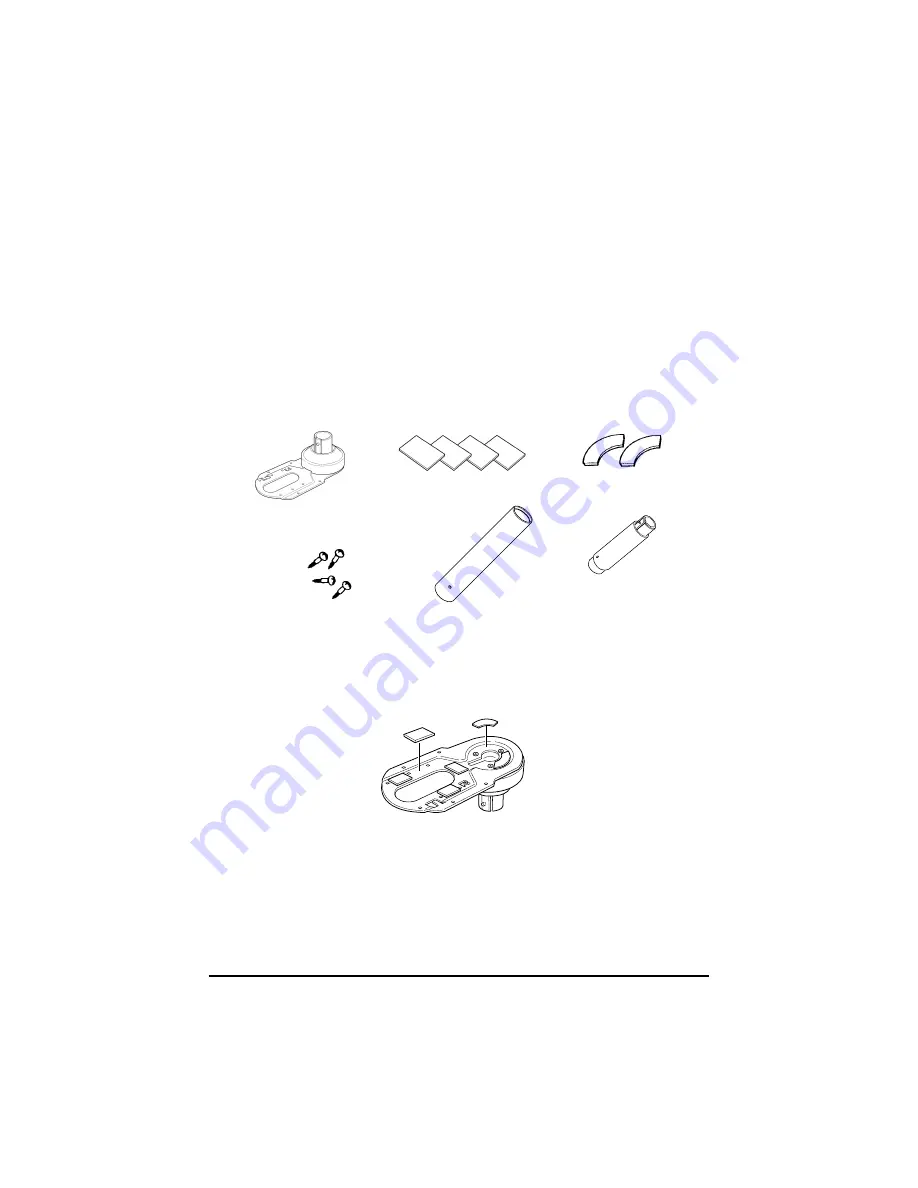
Assembling steps using Velcro tapes

1. Attach Velcro tapes to the bottom of fixing plate A.

fixing plate A

fixing screws for 
wood position

Velcro tapes

Velcro tapes

support C 

support B (for extension)

Содержание DM-D210 Series

Страница 1: ...Customer Display DM D210 Installation Manual 設置マニュアル 安裝手冊 401285101 English ...

Страница 2: ...ser of this product or third parties for damages losses costs or expenses incurred by the purchaser or third parties as a result of accident misuse or abuse of this product or unauthorized modifications repairs or alterations to this product or excluding the U S failure to strictly comply with Seiko Epson Corporation s operating and maintenance instructions Seiko Epson Corporation shall not be lia...

Страница 3: ...n personal injury or in damage to equipment or other property Safety Precautions WARNING Shut down your equipment immediately if it produces smoke a strange odor or unusual noise Continued use may lead to fire or electric shock Immediately turn the power off and contact your dealer or a SEIKO EPSON service center for advice Never attempt to repair this product yourself Improper repair work can be ...

Страница 4: ...or cause injury if it falls A stopper limits the horizontal rotation of the display Do not try to force it to turn beyond the limits of the stopper Doing so may damage the equipment EMC and Safety Standards Applied Product Name DM D210 Type Name M59DB The following standards are applied only to the display that is so labeled EMC is tested using the EPSON PS 170 power supply Europe CE Marking Safet...

Страница 5: ...nd can radiate radio frequency energy and if not installed and used in accordance with the instruction manual may cause harmful interference to radio communications Operation of this equipment in a residential area is likely to cause harmful interference in which case the user will be required to correct the interference at his own expense FOR CANADIAN USERS This Class A digital apparatus complies...

Страница 6: ...TM U675 15 Attaching to Other TM Printers 20 Attaching to the DM D stand 23 Part Names and Functions 30 Exterior 30 DIP Switch 31 DIP Switch Functions 31 Turning and Tilting the DM D210 33 Self Test 34 Check Items of Self test 34 Performing Self test 34 Diagnostics 34 Specification 35 General Specifications 35 Electrical Specifications 38 Environmental Specifications 38 Character Specifications 39...

Страница 7: ...ou use the DM D210 be sure to note the following points Avoid locations that are subject to high temperature and humidity Avoid dirty and dusty locations Avoid locations that are unstable or are subject to high levels of vibration When connecting or disconnecting cables make sure that the power switch of the DM D210 and printers connected to the DM D210 are turned off Do not drop the DM D210 becau...

Страница 8: ...r TM printers Type A DP 502 See page 12 TM H6000 TM U675 You can attach the DM D210 to TM H6000 TM U675 printers using the DM D pole unit for TM printers Type A DP 502 See page 15 Other TM printers You can attach the DM D210 using the DM D pole unit for TM printers Type A DP 502 and Velcro tapes or screws See page 20 DM D stand You can attach the DM D210 to the DM D stand directly using the DM D s...

Страница 9: ... the DM D210 to the IR series These items are packed with the DM D pole unit for IR DP 504 Assembling steps 1 Pass the cable for the DM D210 through support A and attach support A to the DM D210 When using support B for extension insert the tab on support B into the hole on support A until you feel it click base fixing screws support B for extension support A When using support B for extension ...

Страница 10: ... series and secure it with the screws Note When attaching the base note that the corners of the base are set as shown below 3 Pass the cable for the DM D210 through the base 4 Insert the tab on the base into the hole on the support until you feel it click ...

Страница 11: ...attached directly to the TM H5000II TM J8000 printers using the DM D pole unit for TM printers Type B DP 503 Required items The following items are used to attach the DM D210 to the TM H5000II TM J8000 printers These items are packed with the DM D pole unit for TM printers Type B DP 503 base fixing screws support C support B for extension ...

Страница 12: ...nd attach support C to the DM D210 When using support B for extension insert the tab on support B into the hole on support C until you feel it click 2 Attach the base to the setting position on the TM printer and secure it with the screws When using support B for extension ...

Страница 13: ...ish 3 Pass the cable for the DM D210 through the base 4 Insert the tab on the base into the hole on the support until you feel it click 5 Connect the cable for the DM D210 to the DM connector on the TM printer ...

Страница 14: ...re used to attach the DM D210 to the TM U375 TM U950 printers These items are packed with the DM D pole unit for TM printers Type A DP 502 rubber feet square rubber feet large rubber feet square fixing screws for rubber feet large fixing screws for metallic portion fixing screws for plastic position For TM U375 For TM U950 fixing plate A For TM U375 and TM U950 support C support B for extension ...

Страница 15: ...0 through support C and attach support C to the DM D210 When using support B for extension insert the tab on support B into the hole on support C until you feel it click 2 Attach the rubber feet to the printer When using support B for extension TM U375 TM U950 ...

Страница 16: ...e hole on fixing plate A and fix the cable at the bottom as shown below 4 Connect the cable for the DM D210 to the DM connector on the TM printer 5 Adjust the length of the cable and secure fixing plate A to the printer with screws TM U375 TM U950 ...

Страница 17: ...late A on either side of the TM H6000 TM U675 After attaching it you can slide the display freely Required items The following items are used to attach the DM D210 to the TM H6000 TM U675 printers These items are packed with the DM D pole unit for TM printers Type A DP 502 stopper fixing screw for stopper angle fixing screw fixing plate B fixing screws for rubber feet small rubber feet small fixin...

Страница 18: ...rt C and attach support C to the DM D210 When using support B for extension insert the tab on support B into the hole on support C until you feel it click 2 Attach the rubber feet to the printer 3 Attach fixing plate B to the printer When using support B for extension ...

Страница 19: ...e DM D210 to the DM connector on the TM printer 6 Attach fixing plate A to the TM printer using the stopper When you attach the stopper insert the projections on the stopper into the holes of fixing plate B Fixing plate A can be attached on either side of the printer The illustration below shows fixing plate A attached to the right side of the printer ...

Страница 20: ... horizontal rotation mechanism of fixing plate A can be adjusted To secure the location of the display set fixing plate A to either one of the following four positions and secure it with the angle fixing screw ...

Страница 21: ...securing the position of the display make sure that you can open the paper roll cover 8 Store any excess cable in the support and attach the DM D210 to fixing plate A 9 Connect the power cable of the printer To avoid disconnection hook the cable to the tabs on fixing plate B as shown below paper roll cover ...

Страница 22: ...lcro tapes or screws Required items The following items are used when the DM D210 is used with other TM printers These items are packed with the DM D pole unit for TM printers Type A DP 502 Assembling steps using Velcro tapes 1 Attach Velcro tapes to the bottom of fixing plate A fixing plate A fixing screws for wood position Velcro tapes Velcro tapes support C support B for extension ...

Страница 23: ...B for extension insert the tab on support B into the hole on support C until you feel it click 3 Pass the cable for the DM D210 through the hole on fixing plate A and fix the cable at the bottom as shown below 4 Connect the cable for the DM D210 to the DC connector on the TM printer When using support B for extension ...

Страница 24: ...late A 6 Peel off the Velcro tapes and attach the display to the setting position Assembling steps using screws 1 Follow steps 2 and 3 in Assembling steps using Velcro tapes 2 Secure fixing plate A to the setting position with fixing screws 3 Attach the DM D210 to fixing plate A ...

Страница 25: ...red items The following items are used to attach the DM D210 to the DM D stand Note that an optional power unit PS 170 is required when using the DM D stand If DM D210 you want to extend the length of the DM D210 Please get them separately from the DM D stand unit DP 501 extension cable for power supply RS 232C connector installation screw mm type power supply unit PS 170 DM D stand unit for DM Cu...

Страница 26: ... an interface cable which requires millimeter type lock screws replace the inch type screws with the included millimeter type screws using a hex screwdriver 5mm To distinguish the two types of screws see the illustration below printer connector extension cable connector display connector power supply unit connector computer connector millimeter type inch type notch one or more lines RS 232C connec...

Страница 27: ...A 6511 PA 6513 PB 6509 or PB 6510 as the power supply Never connect the DC cable to the power supply unit when the power supply unit is connected Unplug the DC cable by holding the connector part If you pull the cable to unplug it may be damaged JP1 JP2 Contents 1 2 1 2 Set the jumpers as in the left columns when connecting both the TM printer and the DM D stand Default setting 2 3 2 3 Set the jum...

Страница 28: ...rough the DM D stand When extending the length of the DM D stand attach the extension support to the DM D stand 2 Insert the tab on the DM D210 or the extension support into the hole on the DM D stand until you feel it click When using the extension support ...

Страница 29: ...ctor on the DM D stand until you feel it click 4 Connect one end of the computer interface cable to the computer connector on the DM D stand then connect the other end to the RS 232 connector on the computer Tighten the screws on both ends of the cables to fasten them ...

Страница 30: ...he connector on the printer Tighten the screws on both ends of the cable to fasten them 6 When not using the extension cable for power supply packed with the DM D stand go to step 7 When using the extension cable connect it with the arrow mark up to the extension cable connector indicated with POWER OUT on the DM D stand then connect the other end to the power connector on the printer extension ca...

Страница 31: ...hen using as a stand alone product set the jumpers See Jumper setting on page 25 9 Arrange the cables as shown below Put the cables for the DM D210 inside the DM D stand 10 When the extension support is used attach Velcro tapes to the four corners of the plate to avoid falling down 11 Connect the cord of the power unit to the socket DC cable of power supply unit ...

Страница 32: ... switch The power is turned on off DIP switch The functions of the DM D210 are changed See DIP switch for details Note When turning on the DM D210 again after turning it off wait for at least 3 seconds power switch bottom of the display display DIP switch bottom of the display ...

Страница 33: ...ion ON OFF Default setting 1 1 Data receive error Ignored Displays OFF 1 2 Data length 7 bits 8 bits OFF 1 3 Parity on or off Parity No parity OFF 1 4 Parity type Even Odd OFF 1 5 Change transmis sion speed See Transmission speed ON 1 6 OFF 1 7 ON 1 8 Self test selection Perform self test Do not per form OFF SW1 5 SW1 6 SW1 7 Transmission speed bps ON ON ON 2400 OFF ON ON 4800 ON OFF ON 9600 OFF O...

Страница 34: ... switch cover to prevent electrical damage to the DM D210 1 Turn off the power for the DM D210 2 Remove the DIP switch cover 3 Change each setting of the switches with a pointed object such as a pen tip or small screwdriver 4 Close the cover and turn the power on DIP switch cover ...

Страница 35: ...With the DM D pole unit for IR DP 504 and the DM D pole unit for TM printers Type B DP 503 the display area maynot face the direction you desire In this case remove the base change the position of the tab ob the base so that the display faces to the direction you desire and reattach it to the base The display area has the following range of movement Tilt 36 max 3steps 4 positions Horizontal rotati...

Страница 36: ...ps below 1 Turn off the power for the DM D210 2 Set the SW 1 8 of the DIP switch to ON and turn on the power Note If the contents of the self test are not displayed the DM D210 may be malfunctioning Please contact your DM D210 dealer for assistance When the self test is finished and no error occurs the DM D210 is ready to receive data Diagnostics The DM D210 has the diagnostics function When the D...

Страница 37: ...35 English Specification General Specifications Height Width Depth and Weight 260mm 38mm 158mm 110mm 83mm 260mm 503mm DM D210 and DM D stand DM D Stand DP 210 ...

Страница 38: ...600 g DM D stand DP 501 Height 53 mm Width 260 mm Depth 110 mm Weight 385 g DM D pole unit for TM printers Type A DP 502 164 mm 78 mm 260 mm DM D pole unit for TM printer Type B DP 503 DM D pole unit for IR DP 504 50 mm 53 mm 248 mm 129 mm base DM D pole units ...

Страница 39: ...3 Height 248 mm Width 50 mm Depth 53 mm Weight 116 g Fixing plate A and support C of the DM D pole unit for TM printers Type A DP 502 Height 260 mm Width 78 mm Depth 164 mm Weight 264 g Tilt angle Max 36 3 steps 4 positions Horizontal rotation Max 330 Vacuum fluorescent display Number of characters 20 column 2 lines max When using Font B Display color Green 505 nm Brightness 700 cd m2 ...

Страница 40: ...PA 6513 when using the DM D stand Rated voltage DC 11 4 to 48 V Rated current 0 4 A max Environmental Specifications Operation environment Temperature 5 C to 40 C Humidity 30 to 85 No condensation Storage environment Temperature 10 C to 50 C Humidity 30 to 90 No condensation ...

Страница 41: ...rnational characters 37 Extended graphics 128 characters 12 pages Character grid Font 5 7 dot comma period annunciator Character size 3 5 mm x 5 0 mm Character pitch 9 9 mm Reliability Specification MTBF vacuum fluorescent display only 20 000 hours a half value period of the brightness ...

Страница 42: ...40 ...

Отзывы: