background image

Product Information 
 

PSC SVC


______________________________________________________________________________


Subject


to


modification


due


to


technical


advance!


95.700.007.D.E


/


2015

04


6


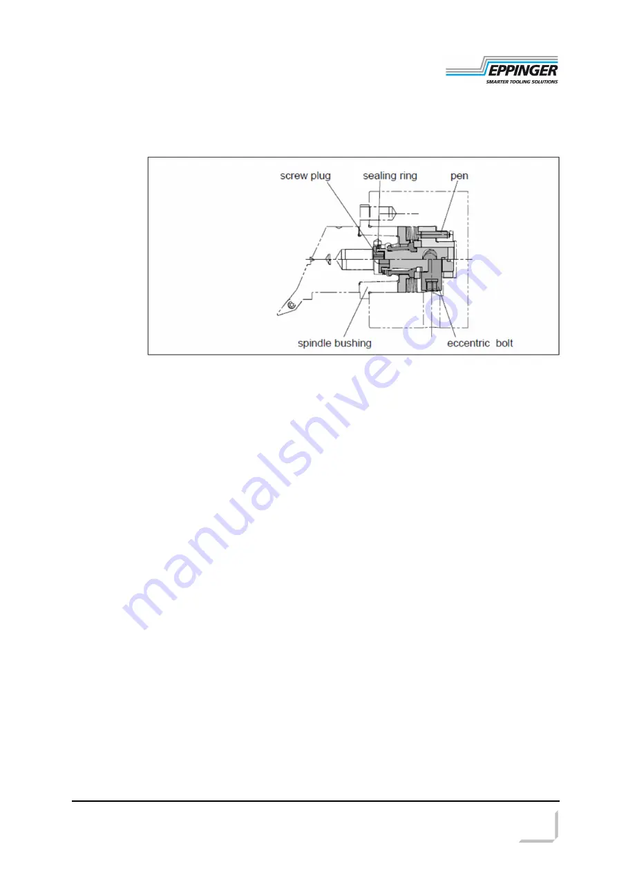
3   Assembly 


  Check 


  Disassembly

  clean and grease inside contour (KLÜBER Wolfracoat C)


  slide in clamping unit;


ensure the correct position pen / hole 
 

  slide in the spindle bushing (interface fit); 

ensure the correct position pen / hole 
 

  fix the spindle bushing 

  test pull-in force;


we recommend: use 

Power-Check


  unscrew the fixing screws of the spindle bushing 


  screw in the setscrews into the threads of the basic holder; let them protrude 


  screw in the screws into the draw-off threads and press out spindle bushing 

uniformly 
 

  pull out clamping unit 

Содержание PSC SVC

Страница 1: ...______________________________________________________ ESA Eppinger GmbH Tel 49 0 711 934 934 0 Email info eppinger de Breitwiesenweg 2 8 Fax 49 0 711 934 934 1 http www eppinger de D 73770 Denkendorf Germany Product Information Manual Clamping Unit PSC SVC for static tool holder ...

Страница 2: ...lfunction Table of contents 1 Safety notes 3 2 Product description 4 2 1 Features 4 2 2 Medium transfer 4 2 3 Pull in force 4 2 4 Order numbers 4 2 5 Dimensions 5 2 5 1 Manual clamping unit PSC SVC 5 3 Assembly 6 4 Operation 7 4 1 Clamp and unclamp 7 5 Maintenance 8 5 1 Preventive maintenance schedule 8 5 1 1 Replace sealing ring 8 5 2 Trouble shooting 9 symbol explanation keep attention dangerous...

Страница 3: ...p water drastically reduces the pH value and causes corrosion on the uncoated parts which often goes unnoticed but later causes severe corrosion damage OTT JAKOB is not responsible for damages if inappropriate coolants are used Notes In order to further improve the product changes of design function and accessories are subject to change without notice The content of this user manual or possible er...

Страница 4: ...Medium transfer nominal size 32 40 50 coolant pressure max bar 20 80 80 higher pressures on request 2 3 Pull in force nominal size 32 40 50 tightening torque max Nm 10 20 30 pull in force kN 15 20 25 2 4 Order numbers nominal size order number 32 24049 40 28684 50 24426 low actuating torque to realize high clamping force pull in force independent of the tightening torque designed for holding PSC h...

Страница 5: ...___ Subject to modification due to technical advance 95 700 007 D E 2015 04 5 2 5 Dimensions 2 5 1 Manual clamping unit PSC SVC Dimensions inside contour see drawing d1 32 40 50 ejection a 0 55 0 55 0 5 A F 5 6 8 l1 49 9 56 55 3 l2 37 3 41 51 5 l3 13 25 0 01 17 25 0 01 21 25 0 01 l4 5 0 02 6 0 02 8 0 02 ...

Страница 6: ...acoat C slide in clamping unit ensure the correct position pen hole slide in the spindle bushing interface fit ensure the correct position pen hole fix the spindle bushing test pull in force we recommend use Power Check unscrew the fixing screws of the spindle bushing screw in the setscrews into the threads of the basic holder let them protrude screw in the screws into the draw off threads and pre...

Страница 7: ... noticeable retarding force finally the stop is distinctly noticeable The pull in force is caused by the spring of the clamping unit not by the tightening torque of the eccentric bolt 4 Operation Always consider the following points The manual clamping unit PSC SVC is only designed for static operation no rotation allowed Only use technically perfect tools 4 1 Clamp and unclamp Clamp Precondition ...

Страница 8: ...ze 32 40 50 order no 24851 24528 24852 regular check if it is damaged or polluted visual check check the sealing ring replace it if necessary 5 1 1 Page 8 test pull in force we recommend use Power Check If the pull in force is smaller than 70 of the nominal value the following procedures have to be performed in the following sequence regrease and test pull force again grease the friction surface w...

Страница 9: ...2 Trouble shooting trouble reason tool is not pulled in correctly wrong or faulty tool inside contour tool feed not correct clamping unit worn out tool is not released accumulated rust on the centering tool is pulled out during work cycle tensioning bolt gripper broken pull in force not sufficient loss of pull force lack of lubrication on clamping set recommendation check pull force ...

Отзывы: