background image

41

RU

Важные указания

• 

 При ненадлежащем монтаже 

существует опасность пожара! Вни-
мательно прочтите настоящее руко-
водство по монтажу. В особенности 
соблюдайте указанные размеры и при-
веденные ниже указания.

•  Этот прибор могут использовать дети 

от 8 лет, а также лица с ограниченны-
ми физическими, сенсорными или 
умственными возможностями, либо с 
недостатком опыта и знаний при усло-
вии нахождения под присмотром либо 
получения указаний о безопасном ис-
пользовании прибора и вытекающего 
из этого понимания опасности. 

•  Детей следует держать под присмо-

тром. Убедитесь в том, что они не игра-
ют с установкой.

•  За детьми необходим постоянный при-

смотр, чтобы они не играли с прибором.

• 

 Монтаж и подключение нагре-

вательного прибора сауны, блока 
управления и других электрических 
приборов к стационарному источнику 
электропитания должны выполняться 
только специалистом. При этом необхо-
димо соблюдать требуемые меры пре-
досторожности, предписанные Союзом 
немецких электротехников в стандарте 
VDE 0100, § 49 DA/6 и VDE 0100, часть 
703/2006-2.

•  Нагревательный прибор сауны и блок 

управления разрешается использовать 
только для кабин саун, изготовленных 
из подходящего необработанного ма-
териала (например, северной сосны) с 
малым содержанием смолы.

•  В кабине сауны разрешается устанав-

ливать только одну печь требуемой 
мощности.

•  В каждой кабине сауны должны быть 

предусмотрены впускные и выпускные 
вентиляционные отверстия. Впускные 
вентиляционные отверстия должны 
быть всегда расположены за нагрева-
тельным прибором на высоте 5-10 см 
от пола. Минимальные размеры впуск-
ных и выпускных вентиляционных от-
верстий указаны в таблице.

•  Вентиляционные отверстия всегда 

располагаются по диагонали от нагре-
вательного прибора в нижней части 
задней стенки сауны. Запрещается за-
крывать вентиляционные отверстия. 
Просьба соблюдать указания вашего 
поставщика сауны.

•  Для регулировки или управления 

нагревательного прибора следует 
использовать один из приведенных 
далее блоков управления. Этот блок 
управления крепится в предназначен-
ном для этого месте на внешней стенке 
кабины, соответствующие корпусы дат-
чиков устанавливаются внутри кабины 

Содержание Moment W

Страница 1: ...VATIVE SAUNA TECH NOLOGY IPx4 Made in Germany Druck Nr 29345183 15 21 EOS Moment Control W D Montage und Gebrauchsanweisung Assembly and operating instruction EN RU Saunaheizger t Sauna heating applia...

Страница 2: ...2 Deutsch 3 English 21 39...

Страница 3: ...5 Hinweis zum Elektroanschluss 7 Lieferumfang 8 Technische Daten 8 Anschlussbeispiel 400 V 3N AC 9 Montage 10 Mindestabst nde 10 Inbetriebnahme und Bedienung 14 Sicherheitsabschaltung 15 Saunasteine 1...

Страница 4: ...peratur werte entstehen und dort auch die Tempera turf hler und Sicherheitsbegrenzer nach den Angaben der Steuerger te Montageanleitung anzubringen sind Beim ersten Aufheizen kann es zu einer leichten...

Страница 5: ...VDE 0100 Teil 703 2006 2zubeachten Saunaheiz und Steuerger t d rfen nur in Saunakabinen aus geeignetem harz armen und unbehandeltem Material z B Nordische Fichte verwendet werden In der Saunakabine da...

Страница 6: ...nschlussleitung und die geeignete Kabinengr e im Verh ltnis zur An schlussleistung in kW entnehmen Sie der Tabelle Technische Daten Bei der Montage des Saunaheizger tes ist darauf zu achten dass der s...

Страница 7: ...ts in dem Wandelement mit der Zuluft ffnung Leerrohre f r die Kabelverle gung eingef gt Sollten in Ihrer Kabine keine Leerrohre vorhan den sein bohren Sie unmittelbar neben dem Saunaheizger t dort wo...

Страница 8: ...H x B x T 64 x 44 x 33 cm F r Kabinenvolumen 9 14 m Mindestma der Be und Entl ftung 35 x 6 cm Gewicht ohne Steine und Verpackung 13 5 kg Steinf llung 15 kg nicht im Lieferumfang enthalten Verbindung N...

Страница 9: ...ussplan sowiedieVorschriftendes rtlichenEVU TAB2000 unddesVDEbeachten Achtung Bauseitig muss in Ofenzuleitung eine ausreichende Absicherung und ein Netztrennschalter installiert werden 400 V 3N AC 5 x...

Страница 10: ...lichen waagerechten Abst ndezwischenHeizger tundKabinenwand sowieOfenschutz Liegebank und anderen brennbaren Materialien entnehmen Sie bitte Abb 1 Achtung StellenSiesicher dassdieMindestabst ndeeingeh...

Страница 11: ...herung nach unten entnehmen Die beigef gten Spanplattenschrauben gem Abb 3 mittig ber der Lufteintritts ffnung an der Kabinenwand befestigen Hierbei mu zum Einh ngen des Saunaheizger tes ein Abstand v...

Страница 12: ...uben verschlie en Achten Sie hierbei darauf dass der Deckel so weit wie m glich unter den Rand des Anschlusskastens geschoben wird Abb 7 Abb 5 Anschlussleitung nach Schaltplan anschlie en Ein Schaltpl...

Страница 13: ...Seiten mit den Schl ssell chern zum Einh ngen immer in der richtigen Position zur Au enseite des Saunaheizger tes hin befinden Jetzt k nnen Sie das Saunaheizger t mit den Schl ssell chern in die berei...

Страница 14: ...unterschiede zwischen der Decke und dem unteren Bereich Hinzukommt dassvieleBimetall Thermometer Wandanzeige sehrtr gereagieren sodassteilweise erst nach ca einer Stunde die wirkliche Temperatur angez...

Страница 15: ...aubendreher zur ck bis Sie einen Schaltpunkt versp ren Abb 10 Der STB befindet sich nun wieder in seiner funktionsf higen Ausgangsposition Sollte der STB nach Inbetriebnahme wieder ausl sen muss das G...

Страница 16: ...steine wieder ausreichend erhitzt ACHTUNG Geben Sie dem Aufgusswasser nie mehr Aufgussmittel oder therische le bei als nach Angaben des Herstellers angegeben Verwenden Sie niemals Alkohol oder unver d...

Страница 17: ...d es k nnen unzul ssige Tempe raturen auftreten Reinigen bzw Entkalken Sie die Ger te bei Be darf Bei eventuell auftretenden M ngeln oder Verschlei spuren wenden Sie sich an Ihren Saunah ndler oder di...

Страница 18: ...esen FI Schalter ab gesichert werden Nach dem heutigen Stand der Technik ist es nicht sinnvoll dampfdichte Rohrheizk rper f r Sauna fen einzusetzen Es kann vorkommen dass die Magnesiumoxidf llung der...

Страница 19: ...ycling Bitte diese Adresse zusammen mit der Montageanwei sung gut aufbewahren Damit wir Ihre Fragen schnell und kompetent beantwor ten k nnen geben Sie uns immer die auf dem Typen schild vermerkten Da...

Страница 20: ...kte sind f r den St ckgut versand Palette konzipiert Wir weisen an dieser Stelle ausdr cklich darauf hin dass unsereVerpackungen nicht f r den Einzelversand per Paketdienst geeignet sind F r Sch den d...

Страница 21: ...connections 25 Scope of delivery 26 Technical data 26 Connection example 400 V 3N AC 27 Sauna heater installation 28 Minimum clearances 28 Commissioning First use 32 Safety cut off 33 Sauna stones 34...

Страница 22: ...he goods or you should contact the company that shipped the goods Please note that you will only be able to achieve anoptimumsaunaclimateifthecabinwithitsair intake and ventilation the sauna heater an...

Страница 23: ...low resin untreatedmaterials e g spruce Only a sauna heater with the appropriate power output may be installed in the sau na cabin Please provide air intake and vent ope nings in each sauna cabin The...

Страница 24: ...floor On heaters with bases this clearance is maintained via the base or legs of the device The sauna heater may not be placed on a floor made of easily flammable material laminate synthetic flooring...

Страница 25: ...the air intake If no empty ducts are available in your cabin drill a sufficiently sized hole in the cabin wall directly next to the place where the cable exits the sauna heater and guide this cable o...

Страница 26: ...onnection 400 V 3N AC 50 Hz Fuse protection 3 x 16 A Equipment size H x W x D 64 x 44 x 33 cm For sauna cabin size 9 14 m Min size air supply and duct vent 35 x 6 cm Weight without stones and packing...

Страница 27: ...f the local power supplier TAB 2000 and the legal norms Caution An adequate fuse and a mains circuit breaker must be installed in the stove s power supply line on site 400 V 3N AC 5 x 1 5 max 10 m 6 0...

Страница 28: ...ty gaps between the heater and the cabin wall or the safety guard rail bench or other flammable materials must be not smaller as indicated in Fig 1 Attention Make sure to observe the safety gaps Risk...

Страница 29: ...ve the lock by pulling downwards Attach the enclosed screws in the centre of the cabin wall above the air intake as shown in Fig 3 There must be a clearance of approx 2 mm between the screw head and t...

Страница 30: ...ews Ensure that the cover panel is pushed under the edge of the terminal box as far as possible Fig 7 Fig 5 Connect the power cable as shown in the wiring diagram There is a wiring diagram attached on...

Страница 31: ...with the keyholes for attachment are always in the right position toward the outside of the sauna heater Now you can hook the keyholes of the sauna heater onto the screws that are screwed into the ca...

Страница 32: ...evelopmentandstability Furthermoreconsiderabledifferencesbetweenthetemperaturesaround the ceiling and in the lower zones are very typical One should also consider that conventional sauna thermometers...

Страница 33: ...ce a click see fig 10 The limiter is now reset and is the standard working position In the case the STB limiter releases again after the heater is switched on please let the heater be checked by a spe...

Страница 34: ...ain Attention Neveraddmoreessencesorvolatileoilsthan advisedonthepackaging Neverusealcohol or undiluted concentrates Caution Fire hazard Sauna rocks Please be sure to note Do not insert sauna rocks to...

Страница 35: ...ded Refer to your sauna supplier or directly to the manufacturer in case of defects or signs of wear and tear Only use original manufacturer s replacement parts which can be obtained from your suppli...

Страница 36: ...ing values during operation for stationary heaters of protection class I 0 75 mA or 0 75 mA each kW input of the appliance depending on the higher value at a maximum value of 5 mA If the appliance is...

Страница 37: ...your questions quickly and compe tently please provide the information printed on the type shield including the model item no and serial no in all inquiries Equipment commissioning date ______________...

Страница 38: ...roducts is designed for the ship ping of individually packed goods pallet We expressly point out that our packaging is not suitable for individual shipments via parcel post The manufacturer shall acce...

Страница 39: ...39 RU 40 40 41 43 45 45 46 47 47 51 52 53 54 55 56...

Страница 40: ...40 RU DIN EN ISO 9001 2015 110 C 30 40 C 110 C 20 25 85 C 80 90 C 76 C...

Страница 41: ...41 RU 8 VDE 0100 49 DA 6 VDE 0100 703 2006 2 5 10...

Страница 42: ...42 RU DIN EN VDE 0100 T 703 40 170 C...

Страница 43: ...43 RU 76 C...

Страница 44: ...44 RU...

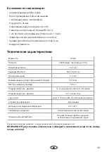
Страница 45: ...45 RU 1 6 5 x 25 4 4 2 x 9 5 6 M 4 x 12 1 3 6 7 5 6 6 9 0 400 3 50 3 x 16 A 64 x 44 x 33 9 14 35 x 6 13 5 15 5 x 1 5 max 10 0 75 40 100 C 22...

Страница 46: ...500 W 9 0 kW 3x 3000 W L1L2L3 N 5 x 2 5 Leuchte Absicherung Hauptschalter Verteilerdose bauseitige Installation L1 A1 A2 A3 L2 L3 N N B1 B2 B3 Thermostat M N PE Zeitschaltuhr timer Thermostat reset A1...

Страница 47: ...47 RU 1 90 90 1 1 2 2 8 cm 33 cm 8 cm 44 cm 8 cm...

Страница 48: ...48 RU 4 3 2 3 4 360 430 180 180 Ma e in mm 2 min 120...

Страница 49: ...49 RU 6 2 6 7 5 7 5 4 2 x 9 5...

Страница 50: ...50 RU 8 6 M4 8 60 cm 22 cm 4 cm...

Страница 51: ...51 RU 45 60 40 100 C 15 C 9 4 30 0 0 0 min max 0 1 2 1 1 2 1 2 2 3 1 2 4...

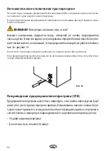
Страница 52: ...52 RU 10 STB 10 STB 30...

Страница 53: ...53 RU 100 10...

Страница 54: ...54 RU 1 2 3 4 4 3 2 1 1 1 2 3 4 4 3 2 1 1 1 1 1 2 2 2 4 3 4 3 3 4 4 4 4 4 1 2 3 4 4 3 2 1 1 1 2 3 4 4 3 2 1 1 1 1 1 2 2 2 4 3 4 3 3 4 4 4 4 4...

Страница 55: ...55 RU EOS Saunatechnik GmbH Schneiderstriesch 1 35759 Driedorf Germany EOC 108811 928 7 495 66 55 192 8 800 1000 539 info eos sauna ru www eos sauna ru...

Страница 56: ...56 RU ASB I II III IV V VI 24 www eos sauna com agb 08 2018...

Отзывы: