background image

6

GB

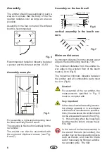
Assembly 

The emitter should be assembled in such a 
way  as  to  ensure  that  the  body  of  the  fre-
quenter  radiates  over  as  large  an  area  as 
possible.

Assembly in the four corners of the infrared 
booth is recommended.

Fig. 4

 Recommended  radiation  distance  between 
a person and the infrared emitter: 30-50 

min 50 cm

min 7 cm

min 9 cm

min 15 cm

IR-Emitter
     Vitae

a

t least 9 cm with

 additional upp

er sea

t

Fig. 5

Assembly example:

For assembly, a right-angled opening must 

be fi tted vertically into the wood.

This opening is fi lled out horizontally for the 
net emitter.

The  emitter  can  then  be  assembled  with 
the  enclosed  chipboard  screws  (see  Fig. 
6 and 7).

Assembly on the booth wall 

Fig. 6

wood border perhaps

appliance should be

aerated in the bac

wood protected  grid

6 cm

7,  cm

cm

cm

cm

5

,5

vertical  assembly  in  the  booth  cor-
ners

 cm

,5 cm

Fig. 7

Minimum distances

he minimum distance from the emitter upper 
edge to the booth ceiling must be 7 cm.

The  minimum  distance  from  the  emitter  lo-
wer  edge  to  the  wooden  fl oor  of  the  booth 
must be 9 cm (Fig.5).

The  horizontal  minimum  distance  between 
the  emitter  and  all  combustible  parts  must 
be 4 cm (Fig.6).


Very important!

In the case of vertical assembly (connec-
tion  always  upwards  or  in  accordance 
with the booth manufacturer‘s specifi ca-
tions), the area above the emitter should 
not be encased with wood in front (Fig. 
1).  Hot air rising when the housing is 
heating must be able to escape freely.  
Fire risk!

In the case of horizontal assembly in 
the area of the nets (net emitter), the 
emitter may not be covered by objects 
such  as  towels,  and  must  be  made 
safe if necessary by fi tting an additio-
nal wooden grille.  Fire risk!

Caution!

For  assembly  of  the  net  emitter,  the 
measurements  specifi ed  in  Fig.  5 
must be complied with.

Содержание IRS 35

Страница 1: ...MADE IN GERMANY IRS 35 50 Druck Nr 29343670en 27 12 GB Assembly and operating instruction...

Страница 2: ...ice 3 Technical data 5 Assembly 6 Assembly example 6 Assembly on the booth wall 6 vertical assembly in the booth corners 6 Minimum distances 6 Service Address 7 Guarantee 7 Handling procedures for ret...

Страница 3: ...53 VDE 0700 Part 53 regulations are to be complied with inside the infrared booth Only the number of emitters specified for the size of the booth should be assembled in the infrared thermal booth Ple...

Страница 4: ...thermal protection slabs to ensure that the wood is not exposed to inadmissible temperatures The infrared thermal emitter is equip ped with a silicon connection cable with a 3 pin connector This conne...

Страница 5: ...k tubes or protected from damage in other appropriate ways To improve the handling of the installation from IR emitter in the cabins is the plug un mounted After the installation of the emitter accord...

Страница 6: ...cmcm 5 5 vertical assembly in the booth cor ners cm 5 cm Fig 7 Minimum distances he minimum distance from the emitter upper edge to the booth ceiling must be 7 cm The minimum distance from the emitte...

Страница 7: ...umber and model name with detailed description of the fault This guarantee covers defective parts and labour but not the defects caused by wear and tear In case of complaint please return the equipmen...

Страница 8: ...ng articles or missing ac cessories He will discuss with you the individual case and try for immediate and customer friendly so lution For economic returns within Germany you will get an RMA number fr...

Отзывы: