background image

18

GB

Initial unit switch-on

After you have checked all of the connections 
once again, connect the unit to the mains by 
switching on all fuses or the main switch.

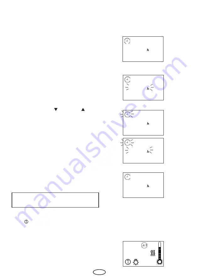
The time appears on the display.

If the display fl ashes, proceed as follows:

With the buttons 

"Ab  "

 and 

"Auf"  „

, you 

can set the required values.

The display shows  

"F1"

 shortly afterwards.

Afterwards,  the current time is shown on the 
display and the unit is ready for use.

To change the time refer to chapter "

F1" 

of 

this operating manual.

The unit is switched on using the left 

"An/

Aus  

"

 button. The cabin lighting and the 

background display illumination are switched 
on at the same time.

Shown on the display:

Confi rm with the 

“Funktion/Mode”

 button.

12:03

20:03

20:03

20:03

06:00

20:03

Содержание EMOTEC HCS 9003

Страница 1: ...1 D IP x4 Made in Germany Druck Nr 29344209en 24 12 EMOTEC HCS 9003 GB Assembly and operating instruction...

Страница 2: ...g a colored light 10 Connecting the remote button 10 Connecting a GSM module 10 Connecting the phase section module for LED spot lights 10 Connecting the switch module for energy saving lamps 10 Insta...

Страница 3: ...gramming levels 30 P1 Starting with the time preselection 30 Deactivating the time preselection 31 P2 Heating time limitation 31 Activation of the weekly timer 32 P0 Weekly timer 32 P1 Starting with t...

Страница 4: ...al connections Bench sensor Art No 94 4389 Humidity sensor Art No 90 9479 Colored light module Art No 94 2761 Neon colored light module Art No 94 4286 EmoLux colored light module Art No 94 4834 Remote...

Страница 5: ...results in automatic shut down after two minutes Lack of water Control characteristic digital two point regulation Fan output min 25W max 100 W max 500 mA only fan excluding capacitor Light min 25W ma...

Страница 6: ...ure gradient towards the floor of the cabin Inversely the relative humidity is lowest directly under the cabin ceiling and the highest on the cabin floor For safety reasons the temperature sensor with...

Страница 7: ...is critical for the tempera ture setting The temperature can be held within operating parameters and a mini mal temperature gradient inside the bench area of the sauna cabin can be achieved only if u...

Страница 8: ...ded 4 x 20 mm wood screws accor ding to Illust 3 3 1 2 Insert one of the wood screws into the upper middle hole This screw will be the mounting point for the control unit Make sure the screw is projec...

Страница 9: ...use a suitable cable duct or a PVC pipe in which you lead the wire s to the power control unit Lead the power cord to the control unit and connect it to the power inlet terminal Electrical connection...

Страница 10: ...ossible from the installation position of the IR lamp may not in the direct beam emo tio n of sau na LSG Connecting a colored light Connecting a GSM module Connecting a power control unit Details can...

Страница 11: ...3 LSG emotio n of sauna Emotec EmoLux F1 F2 X3 X5a X2 Jumper X5 X1 X6 X4 PE L1 L2 L3 N N N U V W WB S1 FAN LIGHT WM L N L N P TEMP SENSOR Nr 2 Nr 1 TEMP LIMITER H SENSOR Ub E G Res 24h 12h 6h 500 mA T...

Страница 12: ...1 FAN LIGHT WM L N L N 400 V 3 N AC 50 Hz 3 kW TB Wb Wm N max 100 W max 100 W P max 9 kW CAUTION When connecting the vapori zer the output W is switched from the sauna heater to the terminal Wb to the...

Страница 13: ...l room P max 9 kW X3 X2 X1 L1 L2 L3 N N N U V W WB S1 FAN LIGHT WM L N L N 400 V 3 N AC 50 Hz max 100 W max 100 W 400 V 3 N AC 50 Hz LSG P max 9 kW X3 X2 X1 L1 L2 L3 N N N U V W WB S1 FAN LIGHT WM L N...

Страница 14: ...up to 2 x 2m according to Illust 7 and 8 in larger cabins according to Illust 7 and 9 2 Drill a hole to lead the cable through pre ferably through the middle of one of the wooden boards 3 Lead the sen...

Страница 15: ...he control unit to the terminals on the right hand side of the lower board The terminals are marked Temp Sensor Nr 2 Bench sensor If there is a problem with the bench sensor a fault message will appea...

Страница 16: ...ing lines 4 x 1 5 mm2 as well Fitting of the humidity sensor optional 1 The humidity sensor is fitted in the centre of the sidewall facing away from the oven at a height of approximately 150 cm 2 See...

Страница 17: ...ror message Ventilation function Lamp Coloured light Operating switch on off Lamp on off Program button Selection buttons If the control box does not pick off voltage after closure please check the po...

Страница 18: ...uf you can set the required values The display shows F1 shortly afterwards Afterwards the current time is shown on the display and the unit is ready for use To change the time refer to chapter F1 of t...

Страница 19: ...g heating time 20 03 05 58 05 58 Temperature display During the heating phase plus approx 15 min utes the thermometer symbol continues to fill The control phase begins once the end tem perature is rea...

Страница 20: ...with the symbols are displayed ash ing on the unit Any change to the set parameters must be saved by pressing the Funktion Mode button The respective newly set values ash brie y before the unit switc...

Страница 21: ...t may be the case that the individual levels are not shown The parameters can be changed here if they have to be frequently adapted to your individual requirements in daily use SAFE The keylock hotel...

Страница 22: ...n In the display appears F1 and the clock symbol Please confirm with the Mode button Please chose the wished value with the and buttons to switch between summer and winter time for example Please conf...

Страница 23: ...ss Mode and button synchron In the display appears F1 and the clock symbol Afterwards press button until F2 in the display appears Please chose the wished value with the and Please chose the wished va...

Страница 24: ...st heating temperature adjustment please press Mode and button synchron In the display appears F1 and the clock symbol Afterwards press button until F3 in the display appears Please confirm with the M...

Страница 25: ...more than 2 minutes the control unit shuts the entire sauna system off for safety reasons For switch off time adjustment please press Mode and button synchron In the display appears F1 and the clock...

Страница 26: ...d Auf you can now set the required value Confirm the entry by permanently pressing the Funktion Mode button until the newly set value flashes on the display Afterwards the F5 is briefly shown until th...

Страница 27: ...the clock symbol Afterwards press button until F6 in the display appears Please confirm with the Mode button Please chose the wished value with the and buttons 1 Humidity sensor activated 0 Humidity s...

Страница 28: ...l Afterwards press button until F8 in the display appears Please confirm with the Mode button Please chose the wished value with the and buttons 1 bench sensor activated 0 bench sensor deactivated Ple...

Страница 29: ...til F10 appears on the display Confirm with the Funktion Mode button Using the Ab and Auf buttons you can now set the required value 5 5 seconds 8 8 seconds 12 12 seconds Confirm the entry by permanen...

Страница 30: ...the An Aus key to start the preselection mode In order to set the time preselection please press the Funktion Mode key The prese lection symbol and P1 will appear on the display With time preselectio...

Страница 31: ...ing the Funktion Mode key until the newly set value ashes on the display Afterwards the P2 is brie y shown until the display issues the basic display Themaximum heating time will now always accord wit...

Страница 32: ...ain Upon initial start up or after a longer period disconnected from the mains time lost the weekly timer is deactivated Activation of the weekly timer Setting the current day of the week In order to...

Страница 33: ...unit before the heating process begins Risk of fire 2 1 07 00 05 40 P1 Starting with time preselection in weekly timer mode P 1 1 P With the keys Ab and Auf please set the required switch on time Conf...

Страница 34: ...iod is 6 h 20 03 10 minutes before a program begins the preselection time is shown alternating with the time of day in the display In this time and during the automatic heating phase the time of day c...

Страница 35: ...t it using the button After starting up the display alternates bet ween the time of day the preset humidity level and the remaining heating time P3 Humid mode P 3 1 1 0 20 03 05 58 60 For humidity ope...

Страница 36: ...with Mode key The humidity operation can be deactivated with the button Please confirm with a long press on the Mode button until the new value is flashing on the display Afterwards the displays shows...

Страница 37: ...press Mode button Afterwards the button until in the display the humidity symbol and P4 appears Please confirm with the Mode button Please chose the wished value with the and buttons P 4 60 80 80 Plea...

Страница 38: ...erwards the button until in the display the heating symbol and P5 appears Please confirm with the Mode button Please chose the wished value with the and buttons The arrow at the thermometer symbol sho...

Страница 39: ...n Afterwards the button until in the display the fan symbol and P6 appears Please confirm with the Mode button Please chose the wished value with the and buttons They mean 0 fan off 1 fan level 1 appr...

Страница 40: ...ting is maximum You can dim the cubicle lighting of your sauna as you wish For illumination power adjustment please press Mode button Afterwards the button until in the display the light symbol and P7...

Страница 41: ...ve the option of operating a coloured light device in your sauna using the HCS 9003 control unit Each coloured light may not exceed the maximum power of 100 W 1 Please chose the wished value with the...

Страница 42: ...loured light mode To do so press the light switch as usual IIf the sauna light is on the coloured light icon does not flash but is shown constantly 20 03 red yellow green blue When the coloured light...

Страница 43: ...P 9 00 02 00 05 00 05 For shining period adjustment please press Mode button Afterwards the button until in the display the colour light symbol and P9 appears Please confirm with the Mode button Plea...

Страница 44: ...unit swit ched off light swit ched on Switching over the heating time limitation for commercial use or wee kly timer Attention Completely disconnect the control unit from the electrical circuit As a s...

Страница 45: ...rror code the warning icon on the screen starts to flash so that it is easy to see that there is an error code To quit after notification of a lack of water error message E511 press the Mode button an...

Страница 46: ...ell as the article code number and type name with expressive description of the fault This warrenty covers damaged parts but no defects due to wear and tear In case of complaint please return the equi...

Страница 47: ...ong articles or missing ac cessories He will discuss with you the individual case and try for immediate and customer friendly so lution For economic returns within Germany you will get an RMA number f...

Отзывы: