SHOULD YOU ENCOUNTER ANY PROBLEMS INSTALLING THIS UNIT CALL
0345 27 27 810
15
SECOND FIX CONT.
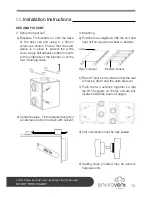
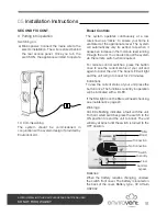
3. Mounting
f) If you are fitting an option summer bypass
ensure 350mm clearance between the
units. Make sure that any ducting fitted
between the two units is insulated and
slopes slightly towards the heat cell.
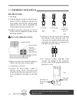
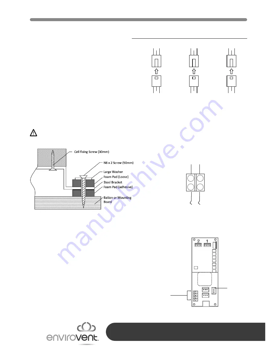
g) Lightly secure the units with 8 x 50mm
screws and the additional rubber mount
and large washers.
Do not over tighten the screws.
h) Make sure that the connection between
the fan unit and heat cell are airtight.
4. Connecting to the unit
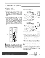
a) Connect the three sensor cables so
that the colours match. The sensors are
located behind the rear panel on the fan
unit and tapped to the spigot on the heat
cell.
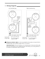
b) Connect to the volt free boost if required
(non-remote control versions only). The
connection is located behind the rear panel
on the fan unit. (See fig.2). Orientation not
important. Closed to boost.
c) On summer bypass specified units,
connect the bypass to the connector
on the control PCB located behind the
electronics cover.
05
Installation Instructions
Switched live
boost input
230V
Summer
bypass
Fig.1
a) Humidity
Black
b) Frost sensor
Blue
c) Internal
temperature
sensor
Red


