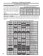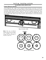
38
Initial Installation
QUALIFIED INSTALLERS ONLY
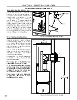
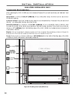
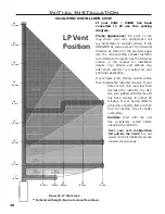
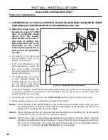
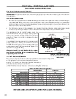
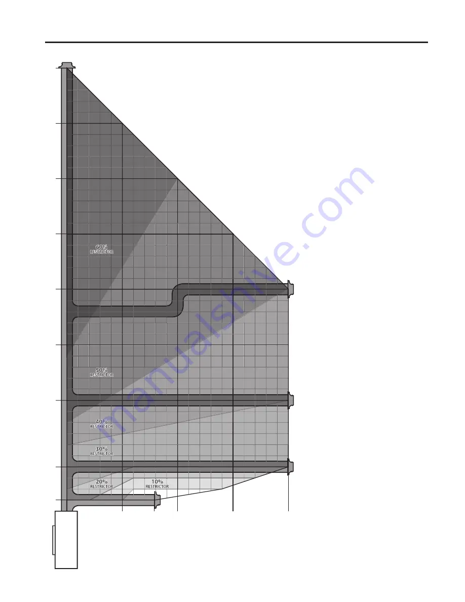
If your C34I / C34ID has been
converted to LP use this venting
diagram.
Flame Appearence:
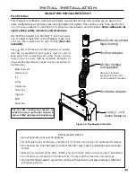
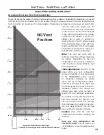
Pin point on the
map where your vent configuration will
lay. Remember to consider elbows in the
HORIZONTAL plane account for horizontal
distance as stated on the previous page.
Use the corresponding exhaust restrictor
accorinding to the graph. See the following
section in this manual for installation
details. Your climate and altitude may
alter what restrictor is required for your
particular application.
If your flame is low, flickery, and more blue
then increase the restrictor one size. If your
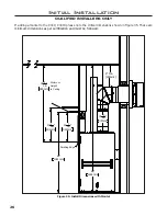
5’
(1.52m)
8’
(2.44m)
4’
(1.22m)
1’
(0.3m)
10’
(3.05m)
10’
(3.05m)
15’
(4.57m)
15’
(1.52m)
20’
(6.1m)
20’
(6.1m)
25’
(7.62m)
30’
(9.14m)
35’
(10.7m)
40’
(12.2m)
LP Vent
Position
flame is tall, thin, and lazy then
decrease the restrictor one size.
Use your judgement after the unit
has been running for about 20
minutes. If your having difficulty
achieving a healthy flame with LP
then try opening the air shutter
completely.
Caution: Wait until the unit
has completely cooled before
changing the restrictor.
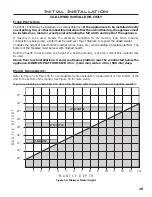
Figure 49: LP Vent Graph
**Vertical vent height does not account for elbows
Does your vent configuration
fall outside the limits?
Use our
power vent kit (50-3884) for a much
broader venting range.
Содержание C34I
Страница 55: ...55 Parts Diagram 1 2 3 5 4 10 8 7 9 12 13 14 6 11 15 ...
Страница 57: ...57 Notes ...
Страница 58: ...58 Notes ...

