


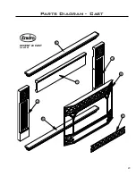


14
Remove the vent collar plate from the top of the insert. It is recommended that a bead of Mil-Pac is
placed on the outer edge of the inner exhaust pipe (non-flared end) before it is connect securely to the
vent collar with sheet metal screws and/or hose clamps. Check for any tears in the liner at this point.
IMPORTANT
: The screws that hold the vent collar plate in its approved position must be installed.
G
AS
L
INE
C
ONNECTION
:
Warning:
Only persons licensed to work with gas piping may make the necessary gas connections to
this appliance.
Gas Line Connection:
• This fireplace is equipped with a certified flexible pipe located on the right side of the unit, terminating
in a 3⁄8 inch male NPT fitting. Consult the local authorities for local codes or use the CAN/CGA B149 (1
or 2) installation code in Canada. In the US, gas installations follow either local codes or the current
edition of the National Fuel Gas Code ANSI Z223.1.
• The efficiency of this unit is a product thermal efficiency rating determined under continuous operating
conditions and was determined independently of any installed system.
The appliance and its shut-off valves must be
disconnected from the gas supply piping system during
any pressure testing where the pressure
exceeds
1⁄2
psig (3.45 kPa) or the valve will be damaged.
The unit must be isolated from the gas supply piping
system by closing its individual manual shut off valve
during any pressure testing of the gas supply piping
system at pressures
equal to or less than
1⁄2 psig
(3.45 kPa)
Always check for gas leaks with a soap and
water solution after completing the required
pressure test.
Main Burner
Natural Gas
(inch WC/KPa)
Propane Gas
(inch WC/KPa)
Orifice:
#45 DMS
#55 DMS
Manifold Press:
3.8 / 0.95
11.0 / 2.74
Min. Manifold Press:
1.1 / 0.27
2.7 / 0.67
Max. Supply Press:
7.0 / 1.74
12.0 / 2.98
Min. Supply Press:
5.0 / 1.25
11.5 / 2.86
Max. BTU/hr Input:
20,000 (5.9 KW•h)
20,000 (5.9 KW•h)
Min. BTU/hr Input:
10,000 (2.9 KW•h)
10,000 (2.9 KW•h)
Output BTU/hr (fan on)
15,100 (4.24 KW•h) 15,400 (4.5 KW•h)
Output BTU/hr (fan off)
14,000 (4.1 KW•h)
14,400 (4.2 KW•h)
O
L I
T
P
TP
TH
TP
TH
IN
OU
T
H
I
LO
N
OF
O
F
LI
P
T O
��������
�������� ���
�����
�������� ���
������
����
����� ����������
�����
��� �������
����
Figure 8. Gas Control Assembly
Initial Installation
QUALIFIED INSTALLERS ONLY
TO TEST VALVE PRESSURES:
The pressure taps are located on the top
right of the valve. Figure 11.
• Turn set screw 1 turn counterclockwise
to loosen.
• Place
5/16
inch (8 mm) I.D. hose over the
pressure taps.
• Check pressures using a manometer.
• When finished, release pressure, remove
hose and tighten set screw.
NEVER USE AN OPEN FLAME FOR LEAK TESTING.
Table 1: Gas Rating


