Copyright © Entrypass Corporation
ENTRYPASS TECHNICAL – WIRING GUIDE
I2D0
I2D1
LED3
BUZ3
IN5
IN6
GND
NC3
COM3 NO3
NC4
NO4
COM4
VR2+
GND
O2D0 O2D1
LED4
BUZ4
IN7
IN8
IN9
GND
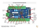
Upper Connector - Only for EP.S3200, EP.S3400, EP.N5200, EP.N5400
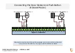
Input 5, 6
Relay 3
Relay 4
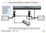
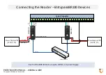
12V/5V Voltage
supply
Input 7, 8
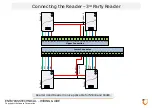
Reader 3
Reader 4
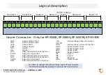
I2D0
- Reader 3 Data 0 Input
I2D1
- Reader 3 Data 1 Input
LED3
- Reader 3 LED
BUZ3
- Reader 3 Buzzer
IN5
- Input 5
IN6
- Input 6
NC3
- Relay 3 Normally Close Connection
COM3
- Relay 3 Common Input
NO3
- Relay 3 Normally Open Connection
NC4
- Relay 4 Normally Close Connection
COM4
- Relay 4 Common Input
NO4
- Relay 4 Normally Open Connection
VR2+
- Supply Voltage Positive Connection
(12V/5V)
GND
- Supply Voltage Ground Connection
O2D0
- Reader 4 Data 0 Input
O2D1
- Reader 4 Data 1 Input
LED4
- Reader 4 LED
BUZ4
- Reader 4 Buzzer
IN7
- Input 7
IN8
- Input 8
IN9
- Reserved
GND
- Inputs Ground
Legend Description
For VR2+ to supply 12V, please make sure JP7 is at 1-2 pins
For VR2+ to supply 5V, please make sure JP7 is at 2-3 pins


