READ & WRITE DATA WITH EXTERNAL DEVICES
MODBUS
130 |
P a g e
Copyright © 2021 BF ENTRON and/or its affiliates. All rights reserved
Product Model:
iPAK2v2
Firmware Version:
V2.10
May 22 | Doc No 700253-2
8.2.3
Outputs
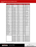
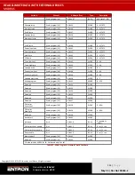
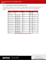
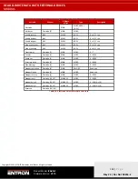
The Modbus Master (PLC or the other Modbus devices) can read the iPAK2v2 control’s output status data through
Function code 3 call. The Modbus addresses for the outputs data are Hexadecimal number #9000 to #9017 (Decimal
number 336864 to 36887).
The data structure of the Inputs data is shown in
Variable
Channel
Address
Type
Description
Read outputs
%IW0
WORD
ARRAY
[0..23]
Read holding registers
Read outputs [0]
%IW0
WORD
READ 16#9000 (= 36864)
EOS
Bit 0
%IX0.0
BOOL
HAV
Bit 1
%IX0.1
BOOL
Fault
Bit 2
%IX0.2
BOOL
Ready
Bit 3
%IX0.3
BOOL
Contactor
Bit 4
%IX0.4
BOOL
Counter
Bit 5
%IX0.5
BOOL
Stepper
Bit 6
%IX0.6
BOOL
Pre-warn
Bit 7
%IX0.7
BOOL
AV8
Bit 8
%IX1.0
BOOL
AV7
Bit 9
%IX1.1
BOOL
AV6
Bit 10
%IX1.2
BOOL
AV5
Bit 11
%IX1.3
BOOL
AV4
Bit 12
%IX1.4
BOOL
AV3
Bit 13
%IX1.5
BOOL
AV2
Bit 14
%IX1.6
BOOL
AV1
Bit 15
%IX1.7
BOOL
Read outputs [1]
%IW2
WORD
READ 16#9001 (= 36865)
Start
Bit 0
%IX2.0
BOOL
≘
%QX0.0
Weld on
Bit 1
%IX2.1
BOOL
≘
%QX0.1
Stop
Bit 2
%IX2.2
BOOL
≘
%QX0.2
Transformer thermal
Bit 3
%IX2.3
BOOL
≘
%QX0.3
2nd stage
Bit 4
%IX2.4
BOOL
≘
%QX0.4
Retract
Bit 5
%IX2.5
BOOL
≘
%QX0.5
Reset fault
Bit 6
%IX2.6
BOOL
≘
%QX0.6
Reset counter
Bit 7
%IX2.7
BOOL
≘
%QX0.7
Reset stepper
Bit 8
%IX3.0
BOOL
≘
%QX1.0
Reserved
Bit 9
%IX3.1
BOOL
Reserved
Bit 10
%IX3.2
BOOL
Reserved
Bit 11
%IX3.3
BOOL
Reserved
Bit 12
%IX3.4
BOOL
Reserved
Bit 13
%IX3.5
BOOL
Reserved
Bit 14
%IX3.6
BOOL
Reserved
Bit 15
%IX3.7
BOOL

