4
5
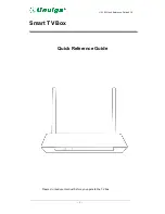
Front Panel
Item
Description
Function
1
Power
Solid blue indicates the unit is on.
Solid red indicates the unit is in standby mode.
Flashing blue indicates the unit s booting up.
Press button once to put unit in standby mode,
press again to resume.
To reboot the device, press and hold button for
at least five seconds.
2*
SD Card Reader
To read or transfer content from a compatible
SD flash memory card.
3*
USB Port
To connect USB devices such as USB flash drive
and external USB hard drive (max 500mA load).
4
Link Indicator
Blue dot indicates that Ethernet or Wi-Fi network
connection is active.
5
Clock
Displays current time set by your service provider.
May not display time while unit is booting up.
6
Record Indicator
Blue dot indicates current program is currently recording.
7
HD Indicator
Blue dot indicates current program is playing
in HD (720p of higher) resolution.
8
USM Port
For inserting a Universal Storage Module
(USM) hard drive.
* Some functions are not available.
Back Panel
Item
Description
Function
1
TV Out
For connecting to an RF TV for loop-through.
(For Amulet 505, it should NOT be connected to
in-house cable network).
2
Composite Video
For connecting to a standard-definition TV (SDTV).
3
Audio
For connecting stereo audio output (Left/Right)
4
Component Video
For connecting to a high-definition TV (HDTV).
5*
IR Blaster Port
For connecting to an IR Blaster.
6
Digital Audio
For connecting to an entertainment system
that supports 5.1 Surround Sound audio.
7
HDMI
For connecting to a high-definition TV (HDTV).
8
Ethernet
For connecting to a wired network.
9*
USB
For connecting USB devices such as USB flash drives
and external USB hard drives (max 500mA load).
10
DC Power Jack
For connecting to a power source
(100-240V, Output 12V/3A).
System Configuration
1
2
3
4
5
6 7
8
1
2
3
4
5 6
7
8 9 10
* Some functions are not available.


