


xiii
Figures
1-1
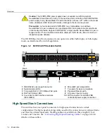
B2G124-48P Stackable Switch ..............................................................................................1-3
1-2
B2H124-48P Stackable Switch ..............................................................................................1-4
3-3
Mini-GBIC with MT-RJ Connector..........................................................................................3-4
3-4
Mini-GBIC with LC Connector ................................................................................................3-4
3-5
Chassis Bottom, Rubber Feet Placement ..............................................................................3-6
3-6
Area Guidelines for Switch Installation on Flat Surface .........................................................3-8
3-7
Attaching the Rackmount Brackets ........................................................................................3-9
3-8
Fastening the Switch to the Rack...........................................................................................3-9
3-9
High-Speed Stacking Cable Connections ............................................................................3-11
3-10
Connecting AC Power and RPS ..........................................................................................3-15
3-11
DB9 Male Console Port Pinout Assignments.......................................................................3-18
3-12
Connecting an IBM PC or Compatible .................................................................................3-19
3-13
Connecting a VT Series Terminal ........................................................................................3-20
3-14
Connecting to a Modem .......................................................................................................3-21
3-15
Connecting a UTP Cable Segment to RJ45 Port .................................................................3-22
3-16
Four-Wire Crossover Cable RJ45 Pinouts for 10/100BASE-TX ..........................................3-23
3-17
Four-Wire Straight-Through Cable RJ45 Pinouts for 10/100BASE-TX................................3-23
3-18
Eight-Wire Crossover Cable RJ45 Pinouts for 10/100/1000BASE-TX.................................3-24
3-19
Eight-Wire Straight-Through Cable RJ45 Pinouts for 10/100/1000BASE-TX ......................3-24
3-20
Cable Connection to MT-RJ Multimode Fiber-Optic Connectors .........................................3-26
3-21
Cable Connection to LC Fiber-Optic Connectors.................................................................3-29
4-22
B2G124-48P LANVIEW LEDs ...............................................................................................4-2
4-23
B2H124-48P LANVIEW LEDs................................................................................................4-3
4-24
Reset Switch ..........................................................................................................................4-9
A-1
Console Port Pinout Assignments......................................................................................... A-7
Tables
1-1
Powered Device Classifications .............................................................................................1-5
1-2
Description of Mini-GBICs......................................................................................................1-6
3-3
Contents of Switch Carton .....................................................................................................3-2
4-4
LANVIEW LED Diagnostic Indications ...................................................................................4-4
4-5
Troubleshooting Checklist......................................................................................................4-7
A-1
Switch Specifications ............................................................................................................ A-1
A-2
Mini-GBIC Input/Output Port Specifications .......................................................................... A-3
A-3
MGBIC-LC01/MGBIC-MT01 Optical Specifications .............................................................. A-4
A-4
MGBIC-LC01/MGBIC-MT01 Operating Range ..................................................................... A-4
A-5
MGBIC-LC03 Optical Specifications ..................................................................................... A-4
A-6
MGBIC-LC03 Operating Range ............................................................................................ A-5
A-7
MGBIC-LC09 Optical Specifications ..................................................................................... A-5
A-8
MGBIC-LC09 Operating Range ............................................................................................ A-5
A-9
MGBIC-08 Optical Specifications.......................................................................................... A-6
A-10
MGBIC-08 Operating Range................................................................................................. A-6
A-11
MGBIC-02 Specifications ...................................................................................................... A-6
A-12
Compliance Standards.......................................................................................................... A-7
Содержание SecureStack B2 B2G124-48P
Страница 2: ......
Страница 12: ...x ...
Страница 21: ...x ...
Страница 25: ...xiv ...
Страница 29: ...Conventions Used in This Guide xviii About This Guide ...
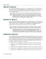
Страница 41: ...1000BASE T Network 2 4 Network Requirements ...
Страница 81: ...Using the Reset Switch 4 10 Troubleshooting ...
Страница 89: ...Regulatory Compliance A 8 Specifications ...


