


Configuring the Switch
3-124
3
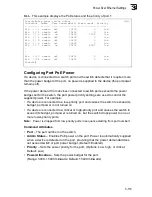
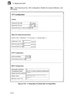
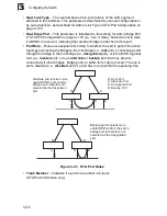
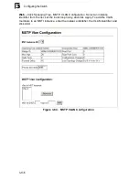
Figure 3-78. Spanning Tree BPDUs
Once a stable network topology has been established, all bridges listen for Hello
BPDUs (Bridge Protocol Data Units) transmitted from the Root Bridge. If a bridge
does not get a Hello BPDU after a predefined interval (Maximum Age), the bridge
assumes that the link to the Root Bridge is down. This bridge will then initiate
negotiations with other bridges to reconfigure the network to reestablish a valid
network topology.
RSTP is designed as a general replacement for the slower, legacy STP. RSTP is
also incorporated into MSTP. RSTP achieves must faster reconfiguration (i.e.,
around one tenth of the time required by STP) by reducing the number of state
changes before active ports start learning, predefining an alternate route that can be
used when a node or port fails, and retaining the forwarding database for ports
insensitive to changes in the tree structure when reconfiguration occurs.
When using STP or RSTP, it may be difficult to maintain a stable path between all
VLAN members. Frequent changes in the tree structure can easily isolate some of
the group members. MSTP (an extension of RSTP) is designed to support
independent spanning trees based on VLAN groups. Once you specify the VLANs to
include in a Multiple Spanning Tree Instance (MSTI), the protocol will automatically
build an MSTI tree to maintain connectivity among each of the VLANs. MSTP
maintains contact with the global network because each instance is treated as an
RSTP node in the Common Spanning Tree (CST).
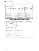
Displaying Global Settings
You can display a summary of the current bridge STA information that applies to the
entire switch using the STA Information screen.
Field Attributes
•
Spanning Tree
State
– Shows if the switch is enabled to participate in an
STA-compliant network.
•
Bridge ID
– A unique identifier for this bridge, consisting of the bridge priority and
MAC address (where the address is taken from the switch system).
x
Designated
Root
Designated
Port
Designated
Bridge
x
x
x
Root
Port
x
Содержание Matrix-V V2H124-24P
Страница 2: ......
Страница 8: ...Notice vi...
Страница 22: ...Contents xx...
Страница 26: ...Tables xxiv...
Страница 30: ...Figures xxviii...
Страница 38: ...Introduction 1 8 1...
Страница 50: ...Initial Configuration 2 12 2...
Страница 159: ...Port Configuration 3 109 3 Figure 3 66 Displaying Etherlike and RMON Statistics...
Страница 234: ...Configuring the Switch 3 184 3...
Страница 480: ...Command Line Interface 4 246 4...
Страница 496: ...Index Index 4...
Страница 497: ......
Страница 498: ...Part 150200039400A FW 2 5 2 0 E012005 R02 ES3526G E072000 R04...


