Page 12
Copyright Enphase Energy Inc. 2011
141-00013 Rev 03b
Installation Procedure
Installing the Engage Cable and Accessories involves several key steps:
1.
Measure AC at Service Entrance Conductors
2.
Install the AC Branch Circuit Junction Box
3.
Position the Engage Cable
4.
Attach the Microinverters to the Racking
5.
Dress the Engage Cable
6.
Terminate the Unused End of the Engage Cable
7.
Connect the Engage Cable to Junction Box(es)
8.
Verification and Commissioning
Risk of Electrical Shock.
Due to presence of exposed
conductors, DO NOT connect the Enphase Microinverters to
the utility grid or energize the AC circuit(s) until you have
completed all of the installation procedures as described in
the following sections.
Step 1 – Measure AC at Service Entrance Conductors
Measure AC line voltage at the service entrance conductors. Acceptable ranges
are shown in the following table.
240 Volt AC Split Phase
208 Volt AC 3 Phase
L1 to L2
211 to 264 Vac
L1 to L2 to L3
183 to 229 Vac
L1, L2 to neutral
106 to 132 Vac
L1, L2, L3 to neutral
106 to 132 Vac
Be sure the Engage Cable you are using matches the service
at the site. Use 208Vac cabling at sites with three-phase
208Vac service, or use 240Vac cabling at sites with 240Vac
service. Check the labeling on the cable drop connectors to
verify the cable type.
Содержание ET10-208-30
Страница 1: ...Installation Manual Enphase Engage Cable and Accessories ...
Страница 4: ...Page 4 Copyright Enphase Energy Inc 2011 141 00013 Rev 03b ...
Страница 6: ...Page 6 Copyright Enphase Energy Inc 2011 141 00013 Rev 03b ...
Страница 24: ...Page 24 Copyright Enphase Energy Inc 2011 141 00013 Rev 03b ...
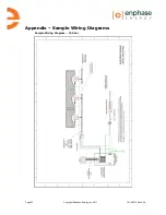
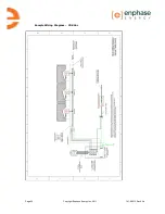
Страница 26: ...Page 26 Copyright Enphase Energy Inc 2011 141 00013 Rev 03b Sample Wiring Diagram 208 Vac ...
Страница 27: ......


