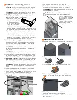
Mount the IQ Battery(ies) on the wall
*
WARNING
: Risk of injury. Take care when lifting.
Each IQ Battery base unit is heavy (44.2 kg/ 97 lbs) and re
-
quires two persons to lift.
*
WARNING!
Risk of injury and equipment damage. Avoid
dropping the IQ Battery(ies). Doing so may create a hazard, cause
serious injury, and/or damage the equipment.
*
WARNING!
Risk of injury and equipment damage. Protect the
IQ Battery(ies) from impact damage and improper use.
A ) Two person together must lift a single IQ Battery base unit from
the packaging and place it right side up on a flat surface.
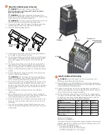
B ) Locate the IQ Battery lifting handles:
C ) If installing multiple battery units, plan to install the IQ Battery
unit located closest to the main supply.
D ) The first person lifting must slide the longer front handle under
the front edge of the IQ Battery, then tilt the handle up so that
handle tabs engage with the slots on the front side of the
battery.
E ) The second person lifting must slide the shorter side handle
under the left or right side (as needed) of the IQ Battery, and
support the upper back of the IQ Battery with their free hand.
F ) Together, lift the IQ Battery and bring it to the already mounted
bracket.
G ) Hold the IQ Battery at an angle so the top of the unit sets into
the top of the wall-mount bracket.
*
WARNING!
Risk of injury and equipment damage. Do not
release the IQ Battery unit until you ensure that the IQ Battery
unit is fully seated in the wall-mount bracket shelf.
H ) Once the top of the battery is engaged with the top tabs of the
wall-mount bracket, keep the battery vertical, make sure the
battery is flush against the bracket, and lower the battery down
until fully seated with the wall-mount bracket and set into the
bracket shelf.
I ) Remove the handles and reserve for the next IQ Battery
installation.
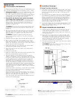
J ) Use a Phillips screw driver to loosen the screws securing the
field wiring compartment cover and remove the cover. Keep the
cover and screws handy as you will need them later.
K ) Attach the battery to the mounting bracket aligning the screw
hole at the top of the battery with the screw hole at the top of
the bracket.
L ) To record the installation of each IQ Battery base unit, scan
the serial number label using Enphase Installer App™ and your
mobile device.
5
Top screw hole
DC Switch
Scannable serial
number label
IQ Battery
IQ Battery
IQ Battery front
handle
IQ Battery side
handle
Install conduit and field wiring
+
DANGER!
Risk of electric shock. The DC switch must be in the
Locked position before performing this step.
A ) If not already done, use a Phillips screw driver to loosen the screws securing
the field wiring compartment cover and remove the cover. Keep the cover and
screws handy as you will need them later.
B ) Remove the sealing plug for entry into the field wiring compartment. If
installing only one battery or when installing the last battery in the array,
seal up the hole with the supplied sealing plug.
C ) Size the conductors (Lines and Ground) to account for voltage rise and
to conform to the tables below. Design for a voltage rise total of less than
2%. IQ Battery can use any circuit breaker size between 10 A and 40 A.
Breaker rating and wire size are installation dependent.
Number of
IQ Battery E3/E10 units
Current
(A)
Minimum wire
size (AWG)
Breaker
rating (A)
1*E3
5.3
14
10
2*E3
10.7
14
15
3*E3 or 1*E10
16.0
12
20
4*E3 or (1*E10 + 1*E3)
21.3
10
30
5*E3 or (1*E10 + 2*E3)
27.7
8
35
6*E3 or 2*E10 or
(1*E10 + 3*E3)
32.0
8
40
*E3 refers to IQ Battery 3
*E10 refers to IQ Battery 10
In all cases in the table, it is possible to always use larger conductors and
a breaker sized for that conductor or smaller. For Example in row 3, with
3*E3 or 1*E10, it is possible to use:
a) 12 AWG wire with 20 A breaker, or
b) 10 AWG wire with 20 A or 30 A breaker, or
c) 8 AWG wire with 30, 35, or 40 A breaker
6

