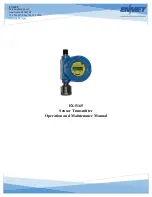


EX-5165
ENMET
Manual Revision Date – June 14, 2017
P a g e
|
8
Manual Part No. – 80003-094
4.2 Normal Display Mode
When the
EX-5165
is installed as described in section 3, and in clean air, the POWER green LED is on, the display is lit and the
information on the display is measurement of the target gas detected by the
EX-5165
.
The red alarm and fault LEDs are not lit.
To advance through displays of operational information tap the magnet over the
M
ENU
button.
N
OTE
:
Software revision may cause variations of display output.
See sequence of operational information below:
Display Measurement of the target gas
Tap the magnet over the
M
ENU
button
Display indicates Alarm 1 Set point
Tap the magnet over the
M
ENU
button
Display indicates Alarm 2 Set point
Tap the magnet over the
M
ENU
button
No Function for the
S
ELECT
button
in this mode
Display indicates Alarm 3 Set point
Tap the magnet over the
M
ENU
button
Display indicates mA Span range
(Full Scale)
Tap the magnet over the
M
ENU
button
Display returns to gas measurement
Operational Display Flow Chart
4.2.1 Alarm Conditions EX-5165
There are three alarm set points available. The alarm set points can be changed within limits; see the maintenance section of
this manual for the procedure.
If the gas concentration increases above that of the alarm set point, the associated red LED is lit.
0%
A1: 5.0
S
ELECT
S
ELECT
M
ENU
M
ENU
A2: 10.0
S
ELECT
M
ENU
A3: 15.0
S
ELECT
M
ENU
mA: 20.0
S
ELECT
M
ENU