191
Installation instructions for professionals
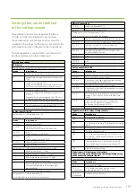
Settings that are not defined
in the settings wizard
The ventilation units are pre-prepared at the factory
in order to shorten the installation time. However,
the possible extras cannot be taken into account for
installation. The settings for the devices connected to the
motherboard must be configured on the control panel.
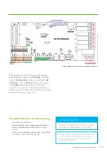
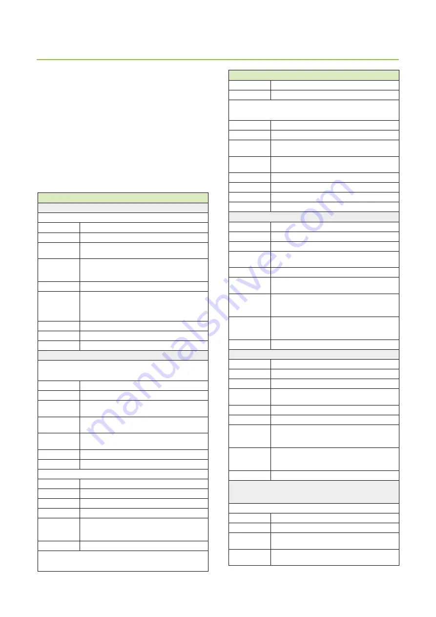
The following table contains the MD card connections
and their placements on the motherboard.
MD card connections
NTC sensors
The MD card has connections for eight (8) NTC-10 sensors.
Intake
Intended use
X1
Outdoor air temperature measuring TE01
X2
Temperature of supply air after heat recovery unit
TE05
X3
Supply air temperature TE10
Supply air temperature after humidity removal coil
TE07 (only units with humidity removal function)
X4
Exhaust air temperature TE32
X5
Exhaust air temperature before heat recovery TE31
(HP only)
Evaporator fluid pipe temperature TE62 (MDX only)
CG radiator freezing guard TE46 (CG-W only)
X6
Pre-heated exhaust air temperature TE50 (HP only)
X7
Pre-warmed outdoor air temperature TE02 (CHG)
X12
Return water temperature TE45
Analog inputs AI 0-10V
Analog inputs AI1–AI6 are between 0–10V.
These input functions are user-defined.
Intake
Intended use
AI1 (X16)
Humidity transmitter 1
AI2 (X16)
Humidity transmitter 2
Water heater temperature TE80 (Aqua only)
AI3 (X16)
(Free)
Supply air duct pressure PDS10
AI4 (X16)
(Free)
Exhaust air duct pressure PDS30
AI5 (X15)
Carbon dioxide transmitter 1
AI6 (X15)
Carbon dioxide transmitter 2
Analog inputs AI1–AI6 have the following functions available:
Humidity transmitter 1, 2, and 3
Carbon dioxide transmitter 1, 2, and 3
Room temperature transmitter 1, 2, and 3
Outdoor temperature transmitter
Pressure difference transmitter PDE10 and PDE30.
These sensors are used in the constant duct
pressure control.
Changing the temperature setting
Analog inputs AI7–AI8 are between 0–5V.
These intake functions are locked by the program.
MD card connections
AI7 (X29)
Exhaust air humidity RH30
AI8 (X29)
Exhaust air temperature TE30
Analog inputs AI9–AI16 are between 0–10V.
These intake functions are locked by the program.
AI9 (X10)
Supply air filter pressure difference PDE01 (extra)
AI10 (X10)
Exhaust air filter pressure difference PDE31 (extra)
AI11 (X10)
Supply air humidity RH10 (only models with
humidity removal function)
AI12 (X10)
Supply air temperature TE10 (only models with
humidity removal function)
AI13 (X10)
Free
AI14 (X10)
Free
AI15 (X10)
Free
AI15 (X10)
Free
Analog outputs AO 0-10V
Output
Intended use
AO1 (X18)
Supply air blower control voltage
AO2 (X18)
Exhaust air blower control voltage
AO3 (X16)
Cooling control voltage / additional post-heating
control voltage (MDX-E/HP-E/HP-W)
AO4 (X18)
Rotating heat exchanger control voltage
AO5 (X16)
Heating control voltage / compressor power control
voltage (MDX/HP)
AO6 (X15)
Pre-heating control voltage / pre-cooling control
voltage (CHG) / HRW n:o 2 control voltage (Twin
Tropic)
AO7 (X15)
Exhaust air pre-heating control voltage (HP) /
exhaust air drying control voltage (TCG) / LTO
de-frosting control voltage (WGHR)
AO8 (X10)
Hot water production control voltage
Digital outputs (DO), relays, closing contacts.
Intake
Intended use
DO1
On/off control of blowers
DO2
On/Off control of heating
DO3
On/off control of cooling / On/off control of heating
(MDX)
DO4
On/off control of LTO
DO5
On/Off control of air locks
DO6
On/Off control of pre-heating / On/Off control of
pre-cooling / On/Off control of heating circulating
pump (Aqua KIW)
DO7
Time-controlled relay / circulation pump on/off
control PU80 (Aqua) / exhaust air cooling on/off
control (TCG)
DO8
A/AB alarm output, closing
Digital inputs (DI) (buttons and indications)
Connection only to the GND terminal (earthing)! Voltage must
not be connected to digital inputs.
The digital inputs are user-defined
Intake
Intended use
DI1 (X16)
Emergency stop (fixed)
DI2 (X16)
user-defined
PDS10 supply air blower pressure switch /
de-frosting indication (MDX/HP)
DI3 (X16)
user-defined
Overtime (only in Office use)
Содержание LTR-3 eAir
Страница 8: ...8 Kanavaliitännät ulkoilma tuloilma poistoilma jäteilma ...
Страница 20: ...20 11 13 9 12 Lisävaruste 1 2 min 10 ...
Страница 48: ...48 ...
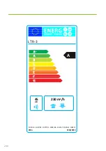
Страница 50: ...50 2016 1254 2014 ENERGIA ЕНЕРГИЯ ΕΝΕΡΓΕΙΑ ENERGIJA ENERGY ENERGIE ENERGI LTR 3 A 45 dB 230 m3 h ...
Страница 51: ...51 Ammattilaisen asennusohje ...
Страница 52: ...52 LTR 3 eAir Installationsanvisningar för ventilationsaggregat Svenska ...
Страница 58: ...58 Kanalanslutningar uteluft tilluft frånluft avluft ...
Страница 70: ...70 9 13 15 11 10 14 Extra tillbehör 1 2 min 12 ...
Страница 98: ...98 ...
Страница 100: ...100 2016 1254 2014 ENERGIA ЕНЕРГИЯ ΕΝΕΡΓΕΙΑ ENERGIJA ENERGY ENERGIE ENERGI LTR 3 A 45 dB 230 m3 h ...
Страница 101: ...101 Installationsanvisningar för yrkesfolk ...
Страница 102: ...102 Installeringsinstruksjoner for ventilasjonsenheten Norsk LTR 3 eAir ...
Страница 108: ...108 Kanalkoblinger utendørsluft tilluft avtrekksluft avkastluft ...
Страница 120: ...120 9 13 15 11 10 14 1 2 min 12 ...
Страница 148: ...148 ...
Страница 150: ...150 2016 1254 2014 ENERGIA ЕНЕРГИЯ ΕΝΕΡΓΕΙΑ ENERGIJA ENERGY ENERGIE ENERGI LTR 3 A 45 dB 230 m3 h ...
Страница 151: ...151 Installasjonsinstrukser for fagfolk ...
Страница 152: ...152 LTR 3 eAir Installation instructions for the ventilation unit English ...
Страница 158: ...158 Duct connections outdoor air supply air extract air exhaust air ...
Страница 170: ...170 9 13 15 11 10 14 Extra 1 2 min 12 ...
Страница 198: ...198 ...
Страница 200: ...200 2016 1254 2014 ENERGIA ЕНЕРГИЯ ΕΝΕΡΓΕΙΑ ENERGIJA ENERGY ENERGIE ENERGI LTR 3 A 45 dB 230 m3 h ...
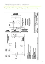
Страница 201: ...201 Mittapiirrokset Måttritningar Måltegninger Dimensional drawings LIITTEET BILAGOR VEDLEGG APPENDICES ...
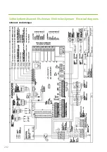
Страница 202: ...202 Sähkökytkentäkaaviot Elscheman Elektriske skjemaer Electrical diagrams Liitännät Anslutningar ...
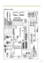
Страница 203: ...203 Koblinger Connections ...
Страница 204: ...204 ...
Страница 205: ...205 ...
Страница 206: ...206 ...
Страница 207: ...207 ...
Страница 208: ...208 ...
Страница 209: ...209 ...
Страница 210: ...210 ...
Страница 211: ...211 ...
Страница 212: ...212 ...
Страница 214: ...214 eAir W Periaatekaavio eAir W Principschema eAir W Prinsippskisse eAir W Principle schema ...
Страница 215: ...215 ...
Страница 218: ...218 ...
Страница 219: ...219 ...

