


ENDEVCO
www.endevco.com Tel: +1 (866) ENDEVCO [+1 (866) 363-3826]
IM 2680/5 083119
11
•
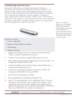
Place airborne amplifier in the preheated oven for a period of time
sufficient for the airborne amplifier to stabilize.
•
Remove the airborne amplifier from the oven
•
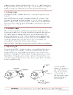
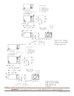
Apply a small amount of rosin core solder (63-37) to the recessed area
around the access screw to form a solder seal (see figure 4).
4.6
How to calculate gain and output level
Any of the methods described in section six may be used. It is necessary
to know the following factors:
Accelerometer’s sensitivity in mV/g (2685) or pC/g (2680)
Desired full-scale output from the airborne amplifier
Determine the amplifiers peak sensitivity in pC/g or mV/g:
(1)
As = Eo
Fs
Where:
As
= Amplifiers charge sensitivity or voltage sensitivity in mV/g.
Eo
= Amplifiers peak full-scale output in mV peak
FS
= Amplifier’s desired peak full-scale output in g peak
The next step is to compute the required gain (Aq):
(2)
Aq = As
Sq
Where:
Sq
= Sensor’s sensitivity in pC/g or mV/g
Make sure that the output signal amplitude is compatible with
the readout equipment:
(3)
As = Eo
Fs
As
= System sensitivity
Where:
Eo
= Output in mV peak
Fs
= Desired full scale (g peak)
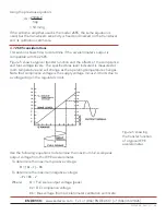
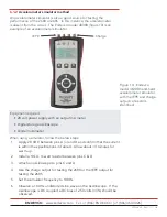
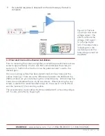
Using one of the signal sources described in section 4, a DMM and/or an
oscilloscope, make the necessary adjustment of the potentiometer. The
signal source should be set 100Hz.
For example, suppose a system consisting of a charge-mode piezoelectric
accelerometer is used to measure ± 50g peak, full scale with a 2680
amplifier (which has a 2500 mV full-scale output).