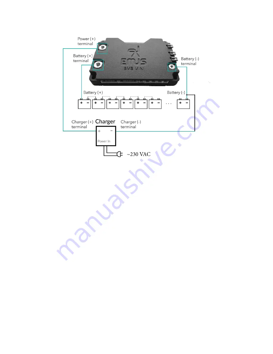
Figure 2.6: Uncontrolled Non-CAN charger installation diagram
eventually one of battery cells will be charged to its maximum voltage and when it tries to rise even
more BMS will trigger ’Over-voltage’ protection and internal contactor will disconnect a charger,
which will finish charging process. For this set-up firstly connect battery to BMS mini: connect
"Battery (-)" to "Battery (-) terminal" and "Battery (+)" to "Battery (+) terminal" using power
cables. Now charger can be connected: using power cables connect "Charger (-) terminal" to
"Battery (-)" and "Charger (+) terminal" to "Power (+) terminal".
10
Содержание BMS Mini
Страница 1: ...EMUS BMS mini User Manual v0 8 1 ...


