delays of the used CAN transceiver and transmission line, and CAN bit timing settings used in CAN-
equipped Emus BMS components. In practice however, lengths with which CAN communication is
reliable may be lower due to use of low grade cables or a high number of connected nodes, therefore
it is recommended to choose the length with the maximum possible reserve when designing the CAN
network. It is also important to note that unterminated drop lines contribute to the total bus length
and thus limit the maximum length of the terminated line.
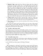
Table 4.1: Maximum bus line lengths, calculated based on the used CAN bit timing setting, considering
that a twisted-pair cable with a typical propagation delay of 5 ns/m is used. L
U
- maximum length of a
single unterminated drop line,
P
L
U
- maximum length of all unterminated drop lines together.
Baud rate
L
U
P
L
U
Max total bus length
1 Mbit/s
2 m
10 m
20 m
800 kbit/s
3 m
15 m
32 m
500 kbit/s
3 m
15 m
45 m
250 kbit/s
6 m
30 m
120 m
125 kbit/s
12 m
60 m
270 m
50 kbit/s
32 m
160 m
770 m
Ideally the topology of the actual CAN network should be as close as possible to a single line
structure, since unterminated drop lines cause signal reflections to occur on the bus, and the longer
they are, the more likely it is for the reflections to continue long enough to cause the node receivers to
misread the signal levels. In practice however, the network is often designed to slightly deviate from
ideal topology for easier installation, yet the both the length of a single drop line and the cumulative
length of all drop lines on the bus should not exceed certain limits, otherwise the reflections may
cause communication errors even though the line is properly terminated. The maximum values of
these lengths in Table
4.1
are calculated based on the bit timing settings used in CAN-quipped
Emus BMS Components, which were chosen according to the recommendations in CiA (CAN in
Automation) 301 standard, and are optimal when nodes from different manufacturers are connected
to the same CAN network.
According to high-speed transmission specification in ISO11898-2 standard, both ends of the
CAN bus must be terminated in order to minimize reflections and ensure that both lines are correctly
returned to a recessive state, because any node on the bus may transmit data. The termination
resistors should match the characteristic impedance of the cable, although the recommended value
is nominally 120
W
(100
W
minimum and 130
W
maximum). There should not be more than two
terminating resistors in the network, regardless of how many nodes are connected, because additional
terminations place extra load on the drivers. ISO-11898-2 standard also recommends not integrating
a terminating resistor into a node but rather using standalone termination resistors. This concept
helps to avoid a loss of a termination resistor if a node containing that resistor is disconnected, and
prevents connecting more than two of them to the bus or locating them at other points in the bus
rather than at the furthest ends.
Maximum number of nodes in a CAN network is limited by their finite differential input resistance
that loads the line and decreases the signal amplitude, therefore it depends on the driving capability
of the used CAN transceiver. The manufacturer of the transceivers used in CAN-equipped Emus
BMS components specifies that it will drive a minimum load of 45
W
, allowing a maximum of 112
nodes to be connected, given that the differential input resistance of each node on the bus is not
less than 20k
W
and 120
W
termination resistor are used.
In order to ensure the robustness and reliability of the CAN network regardless of the conditions
in which it will be used, it is recommended to use a shielded twisted pair cable to implement it.
Due to space saving reasons the CAN interface is populated only on a single connector in all CAN-
21
Содержание BMS Mini
Страница 1: ...EMUS BMS mini User Manual v0 8 1 ...


