
EMTRON EIC USER MANUAL
WWW.EMTRON.WORLD
© EMTRON AUSTRALIA PTY LTD APRIL 2018
28
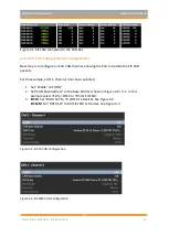
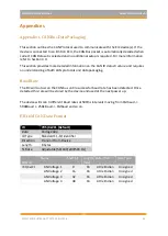
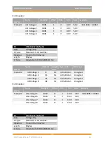
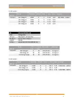
ID
709 /0x2C5 (Default)
Data
Frequency 1dp
ID Type
Standard 11-bit identifier
Direction
Transmit from Device
Length
8 bytes
Tx Rate
Adjustable (50/100/200/500 Hz)
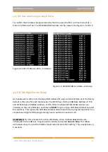
CAN ID
Name
Start bit
Length
(bits)
Byte Order
Data Type
709/0x2C5
Frequency 1
0
16
Little Endian
Unsigned
Frequency 2
16
16
Little Endian
Unsigned
Frequency 3
32
16
Little Endian
Unsigned
Frequency 4
48
16
Little Endian
Unsigned
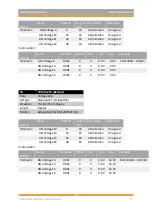
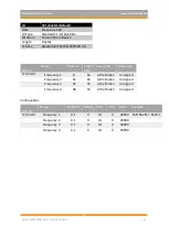
Continuation:
CAN ID
Name
Multiplier
Offset Units
Min
Max
Example
709/0x2C5
Frequency 1
0.1
0
Hz
0
20000 CAN 65201 = 6520.1
Frequency 2
0.1
0
Hz
0
20000
Frequency 3
0.1
0
Hz
0
20000
Frequency 4
0.1
0
Hz
0
20000
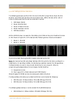
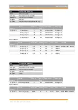
ID
710 /0x2C6 (Default)
Data
Sensor Supply
ID Type
Standard 11-bit identifier
Direction
Transmit from Device
Length
2 bytes
Tx Rate
20Hz
CAN ID
Name
Start bit
Length
(bits)
Byte Order
Data Type
710/0x2C6
5V Analog Supply
0
16
Little Endian
Unsigned
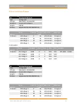
Continuation:
CAN ID
Name
Multiplier
Offset Units
Min
Max
Example
710/0x2C6
5V Analog Supply
0.001
0
V
0.0 V
5.5V
CAN 4989 = 4.989V


