37607-1-0817
Page 31
VENTING FIREPLACE - TOP (continued)
Example of venting system using one 90-degree elbow
Eight feet is minimum vertical vent run with 20 feet of maximum
horizontal vent run. Vertical dimensions are based on center-line
to center-line of pipe. Horizontal dimensions are based on center
line of pipe to end of termination.
SEE GRAPH FOR PERMISSIBLE “H” AND “V” DIMENSIONS
FIRESTOP AT
CEILING LEVEL
Figure 52
Examples of venting systems using two 90-degree elbows.
V is the minimum vertical dimension and total of H1 + H2. V is
also the maximum horizontal dimension. The maximum vertical
and horizontal distances for the two 90-degree elbows as shown
in
Figure 53
is 20 feet (6.1 meters).
FIRESTOP AT
CEILING LEVEL
SEE GRAPH FOR PERMISSIBLE “H” AND “V” DIMENSIONS
NOTE: H1 AND H2 MUST BE ADDED TOGETHER TO USE CHART
Figure 53
B
C
A
CENTER OF ELBOW
STRAIGHT OUT
(MINIMUM)
D
C
B
V
H
FIREPLACE
SERIES
HARD ELBOW DIMENSIONS (in inches)
A
B
C
D
DVCP32
50-13/16
4-5/16
6-5/16
9-1/8
DVCP36
50-13/16
4
6
9-1/8
DVCP42
52-13/16
4
6
9-1/8
FIREPLACE
SERIES
FLEX PIPE 90 DEGREE BEND (in inches)
A
B
C
D
DVCP32
51-11/16
4-1/2
6-1/2
9-1/8
DVCP36
51-11/16
4-1/2
6-1/2
9-1/8
DVCP42
53-11/16
4-1/2
6-1/2
9-1/8
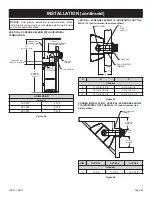
Minimum hole location dimensions for through-the-wall horizontal
installations with 90-degree elbow and 12 inch rise off top of
fireplace.
See Figure 47
on
Page 29
for permissible horizontal and vertical
dimensions.
Figure 54


