background image

37410-0-0616

Page 14

GENERAL   

All furnaces have been fire-tested to check for proper 

operation.  This includes main burner flame, pilot flame, and gas 

control operation.  If the furnace fails to function on initial installation, 

it is advisable to re-check the following: 

1.  Inlet gas pressure.

2.  Type of gas being used and that shown on the rating plate.

Contact your Empire Dealer to assist in servicing furnace.

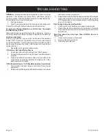
Servicing the Pilot and Main Burner, Pilot orifice, thermopile 

and Main Burner orifice  

Disconnect the gas supply at the inlet to the control valve.   Remove 

the burner assembly to which the above components are attached.

Pilot Does Not Light 

With air in the gas line, such as when the furnace is first installed 

or was "OFF" all summer, the pilot flame may be too lean to ignite 

on the first few trials.  Turn the gas control knob to 

PILOT position 

and depress the gas control knob.  Hold the gas control knob down 

to bleed the line;

1.  Use lighter rod to light pilot with a match.

If Pilot Does Not Light by Any Means 

1.  Check gas control knob for being in the "Pilot" position.

2.  Check pilot adjustment for being full open (counterclockwise 

to open).

3.  If gas is available in the supply tubing, the pilot orifice and/

or pilot burner is probably restricted by a spider web.  Clean 

pilot assembly and relight.

If Pilot Does not Remain "on" After Releasing Gas Control Knob 

1.  Follow instructions and hold gas control knob down longer 

and harder.

2.  Determine if pilot flame extends past thermopile; if not, adjust 

pilot flame or clean pilot burner.

3.  Replace thermopile if millivolt reading is less than 300 millivolts 

when wall mounted on/off device or remote bulb is turned 

OFF. Replace gas control if magnet dropout millivolt reading 

is over 100 millivolts.

Pilot Outage During Normal Operation

1.  Check input by manifold pressure gauge or gas meter.

2.  Check millivolt output when furnace is in operation.  If millivolt 

output decreases during furnace operation gas control may 

be defective. 

Main Gas Valve Does Not Open When ON/OFF Device Is 

Turned "On" 

1.  Check millivolt output of thermopile.

2.  Device wires may be broken.

3.  Device may be defective. 

TROUBLESHOOTING

Содержание GWT-50W

Страница 1: ...r other flammable vapors and liquids in the vicinity of this or any other appliance WHAT TO DO IF YOU SMELL GAS Do not try to light any appliance Do not touch any electrical switch do not use any phon...

Страница 2: ...Ventilation and Combustion Air 8 Location All Models 8 Rough In Instructions 8 9 Finishing Instructions 9 10 Optional On Off Device 11 Lighting Instructions 12 Vent Safety Shutoff System 13 Proper Ma...

Страница 3: ...inspectedbeforeuseandatleast annually by a qualified service person More frequent cleaning may be required due to excessive lint from carpeting bedding materials etc It is imperative that control comp...

Страница 4: ...hts perform service or make adjustments in an area where the conditions are such that you may not detect the odor if there has been a leak of LP Gas Odor fade due to oxidation by rust or adsorption on...

Страница 5: ...57mm above the floor Such equipment shall be located or protected so it is not subject to physical damage by a moving vehicle Qualified Installing Agency Installation and replacement of gas piping gas...

Страница 6: ...as well as condensation of flue products an insulated vent enclosure is recommended Use Type B vent pipe and maintain at least a one inch 25mm clearance to combustibles Use metal thimble to protect ve...

Страница 7: ...at a drip line be installed near the gas inlet This should consist of a vertical length of pipe tee connected into the gas line that is capped on the bottom in which condensation and foreign particles...

Страница 8: ...ts Do not install in a closet alcove or small hallway where the furnace could be isolated by closing doors to the heated space When location is selected check the walls attic and roof to make sure the...

Страница 9: ...finish materials to project into furnace recess 66 1 8 1679 mm WALL OPENING 14 368 mm Figure 4 Installing Furnace Figure 5 Cleartherecessofalldebris andremoveanywoodplaster grounds Stand the furnace...

Страница 10: ...o header with one 1 8 x 3 8 Phillips screw when optional blower is not installed Attention Use outside clearance holes on outer casing top for attachment to header with two 2 8 x 3 8 Phillips screws w...

Страница 11: ...the ON OFF device 4 to 5 feet above the floor on an interior wall not affected by another heating source i e stove or water heater or the temperature of an adjoining room Proper operation depends on a...

Страница 12: ...emove control access panel control door 3 Push in gas control knob slightly and turn clockwise to OFF Do not force 4 Replace control access panel control door 1 Stop Read the safety information above...

Страница 13: ...ner flame with a much larger light blue outer flame The burner does not have a primary air adjustment The flame will be proper if the factory set pressure and orifice are used After the furnace has be...

Страница 14: ...with a match If Pilot Does Not Light By Any Means 1 Check gas control knob for being in the Pilot position 2 Check pilot adjustment for being full open counterclockwise to open 3 If gas is available i...

Страница 15: ...rectly to the service person dealer All parts listed in the Parts List have a Part Number When ordering parts first obtain the Model Number from the name plate on your equipment Then determine the Par...

Страница 16: ...37410 0 0616 Page 16 PARTS VIEW 7 5 6 4 8 9 10 13 16 22 23 24 25 26 20 22 23 26 25 24 21 19 18 9 27 10 11 12 13 17 8 15 14 6 5 7 4 3 2 1 28 12 29 30 30...

Страница 17: ...ll 12 Attach caps and plugs from blower housing and blower front 13 Attach blower front to blower housing with 4 8 x 3 8 screws from Step 6 14 Installation of optional blower assembly is completed Cau...

Страница 18: ...m this plug For an ungrounded receptacle an adapter which has two prongs and a wire for grounding can be purchased plugged into the ungrounded receptacleanditswireconnectedtothereceptaclemountingscrew...

Страница 19: ...ance must be installed by a qualified installer and operated in accordance with the instructions furnished with the appliance A bill of sale cancelled check or payment record should be kept to verify...

Страница 20: ...mpire Comfort Systems Inc Belleville IL If you have a general question about our products please e mail us at info empirecomfort com If you have a service or repair question please contact your dealer...

Страница 21: ...u liquides inflammables dans le voisnage de cet appareil ou de tout autre appareil QUE FAIRE SI VOUS SENTEZ UNE ODEUR DE GAZ Ne pas tenter d allumer d appareil Ne touchez a aucun interrupteur Ne pas v...

Страница 22: ...ons Sommaires 8 9 Instructions pour la Finition 9 10 Installation d un dispositif de marche arr t Mod les SG 11 Instructions d Allumage 12 Le Syst me de Fermeture de S ret de l vent 13 Aspect Convenab...

Страница 23: ...ents nettoyages seront requis Il est imp ratif que les compartiments de commandes les br leurs et les passages de circulation d air de l appareil soient gard s propres Ne rien mettre autour de la four...

Страница 24: ...ces endroits avant d y aller Utiliser le t l phone de votre voisin et appeler les pompiers et une personne entra n e avec le propane Ne pas ouvrir les soupapes d approvisionnement de gaz m me si vous...

Страница 25: ...ns les garages r sidentiels employant du gaz doivent tre install s de fa on ce que les br leurs et les appareils pour allumer les br leurs doivent tre situ s au moins 45 7cm au dessus du plancher Tous...

Страница 26: ...acuation nousrecommandonsd isoler l enceinte d vent Utiliser les tuyaux d vacuation de type B et garder un espace libre d au moins 1 2 54cm aux combustibles Utiliser une bague en m tal pour prot ger l...

Страница 27: ...autorit s ayant juridiction L tat de Massachusetts exige qu une connexion flex ible d un appareil n exc de pas une longueur de trois pieds Test de Pression du Syst me d Alimentation de Gaz 1 Pour v r...

Страница 28: ...er les murs le grenier et le toit pour tre certain qu il n y a pas d obstruction telles que des tuyaux desfils lectriques etc lesquelsentraveraientl installation de la fournaise ou le tuyau d vacuatio...

Страница 29: ...LLECTRICE MONTANTS 2 x4 51mm x 102 mm LAMBOURDE 2 x4 51mm x 102mm 66 1 8 1679 mm OUVERTURE MURALE Basculer la fournaise et ins rer le tuyau d vacuation dans l ouverture rectangu laire dans la plaque c...

Страница 30: ...ibres ext rieurs de la partie su p rieure de la paroi ext rieure pour attacher le collecteur avec deux 2 vis Phillips 8 x 3 8 lorsque la soufflerie facultative est install e 3 Aligner les trous libres...

Страница 31: ...l absence d instructions installez le dispositif de marche arr t 1 2 1 5 m tres 4 5 pieds au dessus du sol sur un mur int rieur qui ne subit pas l effet d une autre source de chaleur po le ou chauffe...

Страница 32: ...er le panneau d acc s aux commandes porte des commandes 11 Allumertoutlepouvoir lectriquedel appareil siapplicable 1 Si l entretien doit tre fait teindre tout le pouvoir lectrique l appareil si applic...

Страница 33: ...t rieure avec une flamme ext rieure bleue p le beaucoup plus grande Il n y a pas d ajustement d air primaire pour le br leur La flamme sera ad quate si la pression pr ajust e l usine et les orifices s...

Страница 34: ...bouton de contr le de gaz il doit tre dans la position Veilleuse 2 V rifier l ajustement de la veilleuse il doit tre compl tement ouvert dans le sens oppos des aiguilles d une montre pour ouvert 3 S i...

Страница 35: ...entretien ou au vendeur Toutes les pi ces num r es dans la liste ont un num ro de pi ce Lorsque vous commandez des pi ces premi rement obtenez le num ro du mod le sur la plaque d identification de l a...

Страница 36: ...37410 0 0616 Page 16 VUE DES PI CES 7 5 6 4 8 9 10 13 16 22 23 24 25 26 20 22 23 26 25 24 21 19 18 9 27 10 11 12 13 17 8 15 14 6 5 7 4 3 2 1 28 12 29 30 30...

Страница 37: ...lerie facultative est compl t e Attention Lorsque vous installez le ch ssis de la soufflerie sur le mur faites attention de ne pas endommager le serpentin du moteur Installation de la soufflerie avec...

Страница 38: ...t tre attach la vis du support de la prise de courant Avec ce fil compl tant la mise terre la fiche de l appareil peut tre branch e dans l adaptateur AVERTISSEMENT D brancher l accessoire de la souffl...

Страница 39: ...37410 0 0616 Page 19 Notes de Service...

Страница 40: ...RE Comfort Systems Empire Comfort Systems Inc Belleville IL Pour toute question g n rale concernant nos produits veuillez nous envoyer un courriel info empirecomfort com Pour toute question d entretie...

Отзывы: