
2
GB | Digital Multimeter
Multimeter MD-220 is a compact, battery-powered, user-friendly
device for measuring alternating and direct current, voltage and
electrical resistance, for testing diodes and transistors and for sound
testing of conductivity. The multimeter was designed in accordance
with the IEC-61010 standard regarding electronic measuring devices
in the category (CAT III 600 V), 2nd degree of pollution.
The CAT III category is used to measure circuits powered by a fixed
output power supply, such as a relay, socket, switchboards, power sup-
plies, short branching circuits and lighting systems in large buildings.
Safety Instructions
• Read this manual thoroughly before using the multimeter.
• Always check the connection of testing conductors and measuring
range settings.
• Do not exceed the maximum input limits:
• for AC and DC voltage: 600 V
• for alternating and direct current: 10 A
• Before changing the measuring range (function), disconnect the
conductors from the measured circuit.
Main Features
LCD display: maximum displed value 1999 (3 and 0.5 digits) with
automatic polarity indication
Measuring method: dual – reacts to the pulse leading and trailing
edge
Maximum standard mode: 500 V DC/AC ms
Reading frequency: approx. 2–3 readings per second
Operating temperature: 23 °C ±5 °C
Temperature range: operating 0 °C to +40 °C; storage –10 °C to
+50 °C
Power supply: 9 V battery (1604 or 6F22). The status of the battery
is indicated by the
icon on the left side of the display
Dimensions and weight: 85 × 165 × 32 mm, 250 g (including the 9
V battery)
Accessories: Instruction manual, measuring tips
Operating Procedure
a. If the device does not turn on (the display does not light up) or
if the
symbol appears on the display upon turning on the
device, the battery is completely drained. Replace the battery.
b. When measuring quantities for which a
symbol is displayed
below the measuring tip connection sockets, do not exceed the
measuring range (risk of damaging the device).
c. If you do not know the approximate voltage or current value
beforehand, set the measuring range to maximum and grad-
ually decrease it as you measure.
d. If the measuring range is exceeded (the display shows the
number "1"), switch to a higher range.
e. Avoid contact with high voltage.
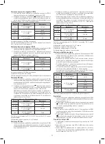
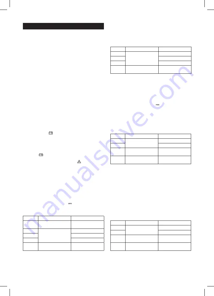
Measuring Direct (DC) Voltage
1. Connect the black measuring tip to the socket labelled as "COM"
and the red conductor to the socket labelled as "V/Ω".
2. Switch to the function marked as V
. Choose a measuring range
and place the measuring tips where you wish to measure DC volt-
age. The voltage value and polarity will be shown on the display.
Follow points c), d), e) of the Operating Procedure!
Range
Accuracy
Deviation
200 mV
±0.5 % of reading
± 1 counts
100 μV
2 V
±0.5 % of reading
± 3 counts
1 mV
20 V
10 mV
200 V
100 mV
600 V
±0.8 % of reading
± 2 counts
1 V
Input impedance: 10 MΩ for all ranges
Overload protection: 250 V rms of peak voltage at 200 mV and
600 V rms in all other ranges.
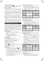
Measuring Alternating (AC) Voltage
1. Connect the black measuring tip to the socket labelled as "COM"
and the red conductor to the socket labelled as "V/Ω".
2. Switch to the function marked as V~. Choose a measuring range
and place the measuring tips where you wish to measure AC
voltage. The measured values will be displayed.
Follow points c), d), e) of the Operating Procedure!
Range
Accuracy
Deviation
2 V
±0.8 % of reading
± 3 counts
1 mV
20 V
10 mV
200 V
100 mV
600 V
±1.2 % of reading
± 3 counts
1 V
Input impedance: 10 MΩ for all ranges
Frequency range: 40 Hz to 400 Hz
Overload protection: 600 V of peak voltage in all ranges
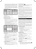
Measuring Direct Current
1. Connect the black measuring tip to the socket labelled as "COM"
and the red conductor to the socket labelled as "mA". To measure
maximum current (up to 10 A), connect the red conductor to the
socket marked as 10 A.
2. Switch to the function marked as A
. Choose a measuring range
and place the measuring tips where you wish to measure DC cur-
rent. The current value and polarity will be shown on the display.
• Maximum input current of 200 mA or 10 A depends on which
socket the red measuring tip is plugged into. Excessive current
will destroy the fuse. In that case, it has to be replaced. The 10
A range is not protected by a fuse and can be measured for a
maximum of 15 s, maximum voltage drop of 200 mV.
Follow points c), d) of the Operating Procedure!
Range
Accuracy
Deviation
2 mA
±0.8 % of reading
± 1 count
1 μA
20 mA
10 μA
200 mA
±1.2 % of reading
± 1 count
100 μA
10 A
±2 % of reading
± 5 counts
10 μA
Overload protection: F 0.2 A/250 V fuse, (10 A range without fuse)
Maximum input current: 10 A, 15 seconds
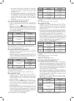
Measuring Alternating Current
1. Connect the black measuring tip to the socket labelled as "COM"
and the red conductor to the socket labelled as "mA". To measure
maximum current (up to 10 A), connect the red conductor to the
socket marked as 10 A.
2. Switch to the function marked as A~. Choose a measuring range
and place the measuring tips where you wish to measure AC cur-
rent. The current value and polarity will be shown on the display.
• Maximum input current of 200 mA or 10 A depends on which
socket the red measuring tip is plugged into. Excessive current
will destroy the fuse. In that case, it has to be replaced. The 10
A range is not protected by a fuse and can be measured for a
maximum of 15 s, maximum voltage drop 200 mV.
Follow points c), d) of the Operating Procedure!
Range
Accuracy
Deviation
2 mA
±1.2 % of reading
± 3 counts
1 μA
20 mA
10 μA
200 mA
±2 % of reading
± 3 counts
100 μA
10 A
±3 % of reading
± 7 counts
10 mA
Overload protection: F 0.2 A/250 V fuse, (10 A range without fuse)
Maximum input current: 10 A, 15 seconds
Frequency: 40 Hz to 400 Hz
Maximum voltage drop: 200 mV
Indicates average value of sine waves.


