
2
3
Resistance Measurement
1. Connect the red test lead to „VmAΩ“ jack and the black test lead to „COM“ jack.
2. Set the Function/Range switch to desired „Ω“ range
3. If the resistence beány measured is connected to a circuit, turn off power and discharge
all capacitors before making measurement.
4. Connect the test leads to the circuit to be measured.
5. Read the resistence value on the LCD.
Diode Measurement
1. Connect the red test lead to „VmAΩ“ jack and the black test lead to „COM“ jack.
2. Set the Function/Range switch to „
“ range.
3. Connect the red test lead to the anode of the diode to be measured and the black test
lead to cathode o fit.
4. The forvard voltage drop in mV will be displayed. If the diod eis reversed, only figure
„1“ will be shown.
Audible Continuity Test
1. Connect the red test lead to „VmAΩ“ jack and the black test lead to „COM“ jack.
2. Set the Function/Range switch to „
“ range.
3. Connect the test leads to the two terminals of the circuit to be tested. If the resistence
is košer than about 50 , the built-in buzzer will sound.
Battery and Fuse Replacement
If „
„ appears on the LCD, it indicates that the battery should be replaced. To replace the
battery, remove the screws on the back cover, and replace the exhausted battery with a
new one of the same ratings.
Fuse rarely needs replacement and is blown generally as a result of operator´s error. To replace
the battery or fuse (F250mA/250V), remove the 2 screws in the bottom of the case, simply
remove the old one, and replace it with a new one of the same ratings.
Accessories
Owner’s Manual: 1 piece
Test leads: 1 pair
9-volt battery: 1 piece
Fuse (F250mA/250V): 1 piece
Disposal of this Article
Dear Customer, Please help avoiding refuse.
If you at some point intend to dispose of this article, then please keep in mind that many of
its components consist of valuable materials, which can be recycled.
Please do not discharge it in the garbage bin, but check with your local council for recycling
facilities in your area.
It is possible to get technical support from the supplier:
EMOS spol. s r.o., Šířava 295/17, 750 02 Přerov I-Město, Czech Republic
This product is not to be used by persons (including children), whose
physical, sensual or mental abilities or lack of ex-perience and knowledge
does not ensure safe use of the appliance, unless they are supervised or
unless they have been
instructed about the use of this appliance by a person in charge of their
safety. Supervision over children is required to prohibit them from playing
with the appliance.
When the product and batteries reach the end of their service life, do not throw them into non
sorted communal waste, use sorted waste collection points instead. By proper
disposal you can avoid negative impact on human health and environment.
Recycling of materials helps to protect our natural resources. You can get more
information about recycling of this product from your municipal authority,
the nearest household waste processing company or the sales point, where
you bought the product.
Declaration of Conformity has been issued for this product.
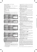
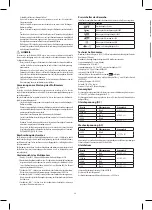
DC Current
Range
Resolution
Accuracy
20 µA
10 nA
±(1.2 % + 5)
200 µA
100 nA
±(1.0 % + 5)
2000 µA
1 µA
20 mA
10 µA
200 mA
100 µA
±(1.2 % + 5)
10 A
10 mA
±(2.0 % + 5)
Overload Protection: 250mA/250V fused (Range 10A unfused).
Measuring Voltage Drop: 200mV
Resistance
Range
Resolution
Accuracy
200 Ω
100 mΩ
±(1.0 % + 5)
2000 Ω
1 Ω
±(0.8 % + 5)
20 kΩ
10 Ω
200 kΩ
100 Ω
2000 kΩ
1 kΩ
±(1.2 % + 5)
Diode and audible continuity
Symbol
Description
The built-in buzzer will sound if the rezistance of the circuit under
test is less than 50 Ω
The approximate forward voltage of diode under test will be
diaplayed on the LCD
OPERATING INSTRUCTIONS
DC Voltage Measurement
1. Connect the red test lead to „VmAΩ“ jack and the black test lead to „COM“ jack.
2. Set the Function/Range switch to desired V range. If the voltage to be measured
is not known beforehand, set the range switch to the highest range and then turn it
down range by range until satisfactory reading is obtained.
3. Connect the test leads to the device or circuit to be measured.
4. Turn on the power of the device to be measured. The voltage value will appear on the
LCD along with the polarity of the red test lead.
When 600V range is exceeded please terminate measuring immediately. Otherwise
electric injury or damage of multimether can occur.
AC Voltage Measurement
1. Connect the red test lead to „VmAΩ“ jack and the blafl test lead to „COM“ jack.
2. Set the Function/Range swithc to desired V~ range. If the voltage to be measured
is not known beforehand, set the range switch to the highest range and then tur nit
down range by range until satisfactory reading is obtained.
3. Connect the test leads to the device or circuit to be measured.
4. Turn on the power of the device to be measured. The voltage value will appear on the
LCD.
When 600V range is exceeded please terminate measuring immediately. Otherwise
electric injury or damage of multimether can occur.
DC Current Measurement
1. Connect the red test lead to „VmAΩ“ jack and the black test lead to „COM“ jack (for
current between 200mA and 10A, connect the red test lead to „10A“ jack).
2. Set the Function/Range switch to desired A range.
3. Open the circuit to be measured, and connect the test leads in series with the load in
which the current is to be measured.
4. Read the current value on the LCD.
Never carry out measuring if voltage is higher than 250 V in open circuit. Such measuring
can lead to damage of multimether (fuse burning or electric discharge) or electric injury.
Before measuring make always sure that you are using the right range of measuring!
MULTIMETER EM391
Read this owner’s manual thoroughly before use
•
Disconnect circuit power and discharge all high voltage capacitors before testing
resistance, continuity, diodes, or capacitance.
•
Use the proper terminals, function, and range for your measurements.
•
Before measuring current, check the meter’s fuse and turn power OFF to the circuit
before connecting the meter to the circuit.
•
Before rotating Function / Range switch to change functions, disconnect test leads
from the circuit under test.
MAINTENANCE
•
Before opening the case, always disconnect the test leads from all live circuits.
•
To continue protection against fire, replace fuse only with the specified voltage and
current ratings: F250mA/250V (Fast Blown) 5× 20mm
•
Periodically wipe the case with a damp cloth and mild detergent. Do not use abrasives
or solvents.
GENERAL DESCRIPTION
This series instruments are compact 3 ½ digit digital multimeters for measuring DC and
AC Voltage, DC Current, Resistance and testing Diode and Audible Continuity. Some of
them also provide Temperature measurement or Battery test function, or can be used as a
signal generator (see the following table). Full range overload protection and low battery
indication are provided. They are ideal instruments for use in fields, laboratory, workshop,
DIY and home applications.
Front Panel Description
1. DISPLAYS – 3 ½ digit LCD, Max. reading 1999
2. FUNCTION / RANGE SWITCH – This switch is used to select the function and desired
range as well as to turn ON/OFF the instrument. To extend the life of the battery, the
switch should be set to the „OFF“position when the instrument is not in use.
3. „10A“ – Plug in connector for the red (positive) test lead for current (between 200mA
and 10A) measurements.
4. „VmAΩ“ JACK – Plug in connector for the red (positive) test lead for all voltage, resistence
and current (up to 200mA)
5. „COM“ JACK – Plug in connector for the black (negative) test lead.
General Specifications
Maximum Display:
1999 counts ( 3 ½ digits) with automatic polarity indication
Indication Method:
LCD display
Measuring Method:
Dual-slope integration A/D converter system
Over range Indication:
Only figure „1“ displayed on the LCD
Reading Rate:
2–3 times/second (approximate)
Operating Temperature:
0 °C–40 °C (32 °F–104 °F), 75 % R.H.
Storage Temperature:
-10 °C–50 °C (14 °F–122 °F), 75 % R.H.
Power Supply:
One 9-volt battery (NEDA1604, 6F22)
Low Battery Indication:
“
” displayed on the LCD
Dimensions/Weight:
138 × 70 × 28 (mm)/115 g (including one 9V battery)
Specifications
Accuracy is specified for a period of 1 year after calibration and at 18 °C–28 °C (64 °F–82 °F)
with relative humidity up to 75 %.
Accuracy specifications take the form of:
+/- (% of R(Number of Lest Significant Digits)
DC Voltage
Range
Resolution
Accuracy
200 mV
100 µV
±(0,5 % + 5)
2000 mV
1 mV
±(0,8 % + 5)
20 V
10 mV
200 V
100 mV
600 V
1 V
±(1 % + 5)
AC Voltage
Range
Resolution
Accuracy
200 V
100 mV
±(1.2%+10)
600 V
1 V
Response: Average responding, calibrated in rms of a sine wave.
Frequency Range: 45 Hz ~ 450 Hz


