background image

CONNECTIONS

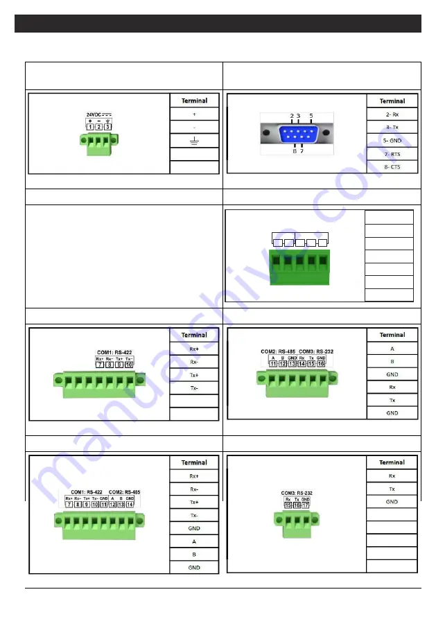
Device Supply Input(For PROOP 4.3,5,7 
and 10 )

COM4 (For PROOP 7 and 10)

COM2- COM3 (For PROOP 4.3, and 5)

COM1 (For PROOP 7 )

COM2- COM3 (For PROOP 7)

COM1 – COM2 (For PROOP 10)

COM3 (For PROOP 10 )

21

Terminal

A

B

GND

Tx

Rx

COM1

RS-485

A

B GND Tx

4    5    6    7    8 

Rx

COM2

RS-232

Содержание Proop Series

Страница 1: ...Professional Operator Panel User Manual...

Страница 2: ...ct to multiple controllers and increase your processing power You can connect to external networks with the Ethernet port or access the HMI panel from an external network again With built in input por...

Страница 3: ...le Format Windows FNT Portable Font Resource PFR Type 42 limited support fonts Remote access and control thanks to the built in VNC protocol Project upload or download in a short time with high speed...

Страница 4: ...Proop 10C Proop 10C wi Proop 10C E Proop 10C Ewi Proop 10P 0 D5 D4 AC AC Proop 10P wi D5 D4 AC AC Proop 10P E D5 D4 AC AC Proop 10P Ewi D5 D4 AC AC Proop 10P E2 D5 D4 AC AC Proop 10P E2wi D5 D4 AC AC...

Страница 5: ...duct 4 3 10 1 5 7 4 3 TFT LCD 260K 480x272 Resistive Analogue LED 530 25 C 50000 Hour ARM Cortex A Series 8GB eMMC 512 MB DDR3 SDRAM X 1 x USB 2 0 1 x USB 2 0 Max Speed 230400 Baudrate Max Speed 57600...

Страница 6: ...RJ45 Ethernet network cable USB Port Input Windows XP Windows Vista Windows 7 Windows 8 Windows 8 1 Windows 10 any of the operating systems DIMENSIONS Proop 4 3 Proop 5 Proop 7 Proop 10 1 AEMKO a b c...

Страница 7: ...n on the panel 4 Install mounting brackets into their slots 5 Secure the device to the panel by tightening the device s apparatus screws 6 Excessive force can damage the panel 7 Screws of the cables a...

Страница 8: ...ld be separated from the high current and voltage line Necessary precautions must be taken for all parts that may create a hazard on the mechanical parts of the device These measures are necessary for...

Страница 9: ...here is a danger arising from any error or malfunction on the device turn off the system s energy and disconnect all electrical connections of the device from the system Do not make changes or attempt...

Страница 10: ...k color options and other models can choose 2 different colors Black and Gray color views are as in Figure 1 and Figure2 Proop Black Proop Grey Figure2 PROOP front view 1 2 3 Figure1 PROOPBLACK front...

Страница 11: ...Figure2 PROOP 7 Back view 10 Figure3 PROOP 10 1 Back view RS 422 RS 422 Digital Outputs Digital Inputs Analogue Digital Outputs Analogue Digital Inputs...

Страница 12: ...rm page and the button type property of this button should be set as HMI settings Figure4 Button Type Setting In the HMI Network settings section Ethernet communication settings can be made for device...

Страница 13: ...to get fixed IP from the network and the necessary settings can be made Related fields become active for Figure7 HMI Time Date Settings Window From the HMI Date and Time settings tab the time and date...

Страница 14: ...Battery in other models The back cover must be opened for replacement Figure8 10 HMI Battery bed Local time zone can be defined from Locale tab When programming local time zone can be read from S12 a...

Страница 15: ...ose the buzzer during the program assignment to S0 must be made When S0 is 1 the buzzer will be open and 0 will be closed S1 address is used to change the screen brightness S1 address is between 0 7 0...

Страница 16: ...made through the Proop PC connection section by following the Project Project Settings path in the editor software When the connection type is selected as Ethernet the IP number of our device should...

Страница 17: ...ble 4 Connect the HMI panel to the Ethernet network 5 PROOP PC Connection from the project settings section in the editor software Choose as Ethernet 6 Type the IP address of the panel in the Destinat...

Страница 18: ...age library file with the extension rcc that you used in your project to this folder where you created it 4 Connect the USB memory to the USB host socket on the back of the HMI device 5 When USB memor...

Страница 19: ...sion bin you downloaded from the site in the window that appears Select the file When the update is installed on the device the device will turn on again and all the program in it will be deleted Firm...

Страница 20: ...on the PC the permanent memory is deleted The non volatile memory of the device is independent of the device supply It is not Volatile Memory Non Volatile Memory Volatile Memory Bit Non Volatile Memo...

Страница 21: ...ral Internal Memory Space Modbus Address Range Start Finish Modbus Functions Volatile Memory Non Volatile Memory Volatile Memory Bit Non Volatile Memory Bit 40001 42001 44001 45001 42000 44000 44002 4...

Страница 22: ...For PROOP 4 3 5 7 and 10 COM4 For PROOP 7 and 10 COM2 COM3 For PROOP 4 3 and 5 COM1 For PROOP 7 COM2 COM3 For PROOP 7 COM1 COM2 For PROOP 10 COM3 For PROOP 10 21 Terminal A B GND Tx Rx COM1 RS 485 A B...

Страница 23: ...Digital Outputs Digital Output Supply Digital Inputs Digital Inputs NPN PNP Selection Wiring Diagram Explanation Analogue Input 2 Analogue Input 1 Digital Inputs Digital Inputs NPN PNP Selection Wiri...

Страница 24: ...solutions containing hydrocarbons such as Petroleum Trichlorethylene Cleaning the device with these solutions can reduce the mechanical reliability of the device OTHER INFORMATIONS Manufacturer Compa...

Отзывы: