Instruction Manual
IM-105-4000, Rev 1.3
October 2008
OPM 4000
3-4
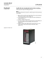
Figure 3-2. OPLR Display
ZERO/SPAN
CALIBRATION CHECK
The zero calibration has been set at the factory by placing the instrument on
an optical bench and using the flange-to-flange dimensions recorded in the
customer’s order. This zero value is critical as it can offset smoke
measurement if not correctly set. The measurement reflector contains an
aperture that is chosen during the factory calibration and is fixed. The
transceiver is aligned with the beam centered on the retro reflector and the
electronics is adjusted to produce a zero opacity value.
The zero jig is then adjusted to provide a low value (typically 1-2%). This
value and the span filter up scale value are recorded and entered in the Quick
Menu under "Zero Cal Value" and "Span Cal Value". When the system enters
a manual or auto cal check cycle, the current zero and span values are
checked against the stored values. If either the zero or span current value
exceeds the stored value by ±2% opacity, the fault system will energize.
To verify the zero/span calibration check, follow the procedure below.
1. Push the CAL. AUTO/MAN key to initiate a manual calibration cycle.
The Alarm LED will light and the left/right bargraph will blink. This is
normal since a manual calibration is considered a fault condition.
2. Press the ACK key. The ALARM LED and bargraphs will stop blinking.
The message display will read MANUAL CAL ALARM.
3. Push the DIS key to return to display opacity.
4. Push the ACK key (after the calibration cycle is complete) to clear any
alarms. If no alarms are present, the system is working properly.
(ESC)
EDIT
ENTER
t
EDIT
u
EDIT
REM
LOC
AUTO
MAN
DIS
ACK
+19999
MESSAGE
I
A
D
“Edit Value” Light
“Scroll Menu” Light
Moves Message Cursor
EDIT Keys
Hinged Cover
ALARM
38450009
ZERO
RUN
SPAN
HIGH
OPACITY
OPERATE
CAL.
Содержание Rosemount Analytical OPM 4000
Страница 2: ......
Страница 6: ......
Страница 10: ...Instruction Manual IM 105 4000 Rev 1 3 October 2008 OPM 4000 TOC 4 ...
Страница 14: ...Instruction Manual IM 105 4000 Rev 1 3 October 2008 OPM 4000 iv ...
Страница 38: ...Instruction Manual IM 105 4000 Rev 1 3 October 2008 OPM 4000 2 16 Figure 2 12 Typical System Wiring ...
Страница 42: ...Instruction Manual IM 105 4000 Rev 1 3 October 2008 OPM 4000 2 20 ...
Страница 52: ...Instruction Manual IM 105 4000 Rev 1 3 October 2008 OPM 4000 4 6 ...
Страница 58: ...Instruction Manual IM 105 4000 Rev 1 3 October 2008 OPM 4000 5 6 ...
Страница 64: ...Instruction Manual IM 105 4000 Rev 1 3 October 2008 OPM 4000 6 6 ...
Страница 100: ...Instruction Manual IM 105 4000 Rev 1 3 October 2008 OPM 4000 A 24 ...
Страница 102: ...Instruction Manual IM 105 4000 Rev 1 3 October 2008 OPM 4000 B 2 ...
Страница 104: ...Instruction Manual IM 105 4000 Rev 1 3 October 2008 OPM 4000 C 2 ...
Страница 110: ...Instruction Manual IM 105 4000 Rev 1 3 October 2008 OPM 4000 D 6 Figure D 5 Retrofit System Wiring Diagram ...
Страница 114: ...Instruction Manual IM 105 4000 Rev 1 3 October 2008 OPM 4000 D 10 ...
Страница 116: ...Instruction Manual IM 105 4000 Rev 1 3 October 2008 Index 2 OPM 4000 ...


