Instruction Manual
IM-105-4000, Rev 1.3
October 2008
2-17
OPM 4000
Duplexer and AC power Supply
1. Connect the line wire (terminal 11 of the control unit) to an AC power
source.
2. Connect the neutral wire (terminal 12 of the control unit) to an AC power
source.
3. The transceiver blower is factory wired to the duplexer.
4. Plug the retro reflector blower into an AC power source.
5. Plug the service module into the duplexer.
6. Plug the duplexer into an AC power source.
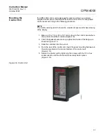
Figure 2-13. P1 and P2 Pin
Designations
Содержание Rosemount Analytical OPM 4000
Страница 2: ......
Страница 6: ......
Страница 10: ...Instruction Manual IM 105 4000 Rev 1 3 October 2008 OPM 4000 TOC 4 ...
Страница 14: ...Instruction Manual IM 105 4000 Rev 1 3 October 2008 OPM 4000 iv ...
Страница 38: ...Instruction Manual IM 105 4000 Rev 1 3 October 2008 OPM 4000 2 16 Figure 2 12 Typical System Wiring ...
Страница 42: ...Instruction Manual IM 105 4000 Rev 1 3 October 2008 OPM 4000 2 20 ...
Страница 52: ...Instruction Manual IM 105 4000 Rev 1 3 October 2008 OPM 4000 4 6 ...
Страница 58: ...Instruction Manual IM 105 4000 Rev 1 3 October 2008 OPM 4000 5 6 ...
Страница 64: ...Instruction Manual IM 105 4000 Rev 1 3 October 2008 OPM 4000 6 6 ...
Страница 100: ...Instruction Manual IM 105 4000 Rev 1 3 October 2008 OPM 4000 A 24 ...
Страница 102: ...Instruction Manual IM 105 4000 Rev 1 3 October 2008 OPM 4000 B 2 ...
Страница 104: ...Instruction Manual IM 105 4000 Rev 1 3 October 2008 OPM 4000 C 2 ...
Страница 110: ...Instruction Manual IM 105 4000 Rev 1 3 October 2008 OPM 4000 D 6 Figure D 5 Retrofit System Wiring Diagram ...
Страница 114: ...Instruction Manual IM 105 4000 Rev 1 3 October 2008 OPM 4000 D 10 ...
Страница 116: ...Instruction Manual IM 105 4000 Rev 1 3 October 2008 Index 2 OPM 4000 ...


