background image

Specifications and Reference Data

January 2019

Reference Manual 

00809-0100-4130, Rev DC

Specifications and Reference Data

41

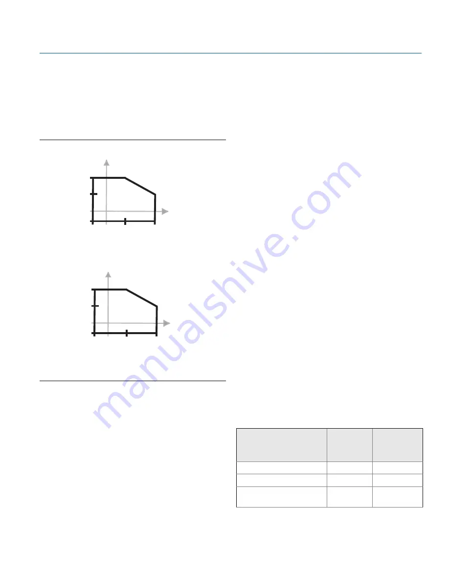
Minimum and maximum operating 
temperatures

See 

Figure A-2

 for operating temperatures.

The ambient temperature for a 8/16 mA cassette is 
limited to 158 °F (70 °C) in potentially explosive dust 
atmospheres.

Figure A-2. Operating Temperatures

A.1.4  Performance

Hysteresis (water)

0.1 in. (± 2.5 mm)

Switching point (water)

0.5 in. (13 mm) from tip of fork (if vertical installation) or 
from edge of fork (if horizontal installation) – this will vary 
with different liquid densities

Liquid density requirement

Minimum standard density is 37.5 lb/ft

3

 (600 kg/m

3

).

Minimum density is 31.2 lb/ft

3

 (500 kg/m

3

) when ordered 

with the low-density range option.

Liquid viscosity range

Up to 10000 cP (centiPoise) when operating in the normal 
mode.

Up to 1000 cP (centiPoise) when operating in self-check 
mode.

Solids content and coating

The maximum recommended diameter of solid particles in 
the liquid is 0.2 in. (5 mm) when used in normal mode only. 
For coating products, avoid bridging of forks.

Switching delay

There is a user-selectable 0.3, 1, 3, 10, 30 seconds delay for 
dry-to-wet and wet-to-dry switching.

CIP (Clean In Place) and SIP (Steam In 
Place) cleaning

Withstands cleaning routines up to 275 °F (135 °C).

NACE

NACE compliance to MR0175 / ISO 15156 or MR0103, 
depending on the option code selected for the model 
number.

Operating modes

Table A-4.  Operating Modes

176 (80)

176 

(80)

-40 (-40)

-94 

(-70)

500 

(260)

Process Temperature °F (°C)

A

m

b

ient

 T

e

m

p

er

at

u

re

 °

C

)

149 (65)

32 (0)

32 

(0)

2130***E

176 (80)

176 

(80)

-40 (-40)

-40 

(-40)

356 

(180)

Process Temperature °F (°C)

A

m

b

ien

t T

e

m

p

er

at

u

re

 °

C

)

122 (50)

32 (0)

32 

(0)

2130***M

Fault conditions detected

Normal 

mode (red 

LED)

Self-check 

mode (yellow 

LED)

PCB control circuit corruption

Yes

Yes

External damage to fork

No

Yes

Internal wire 
disconnection/break

No

Yes

Содержание Rosemount 2130

Страница 1: ...Reference Manual 00809 0100 4130 Rev DC January 2019 Rosemount 2130 Level Switch Vibrating Fork ...

Страница 2: ...ii Section Title January 2019 Reference Manual 00809 0100 4130 Rev DC ...

Страница 3: ...pport quoting and order related questions Americas 1 800 999 9307 Europe 41 0 41 768 6111 Middle east 971 4 811 8100 Asia 65 6777 8211 North American Response Center Equipment service needs 1 800 654 7768 24 hours includes Canada Outside of these areas contact your local Emerson representative The products described in this document are NOT designed for nuclear qualified applications Using non nuc...

Страница 4: ...tact with the leads and terminals Make sure the main power to the level switch is off and the lines to any other external power source are disconnected or not powered while wiring the level switch Ensure the wiring is suitable for the electrical current and the insulation is suitable for the voltage temperature and environment External surfaces may be hot Care must be taken to avoid possible burns...

Страница 5: ...nsiderations 8 2 2 2 Environmental considerations 8 2 2 3 Application considerations 9 2 2 4 Installation considerations 11 2 2 5 Installation recommendations 12 2 2 6 Installation examples 15 2 3 Installation procedures 16 2 3 1 Mechanical 16 2 3 2 Correct fork alignment 17 2 3 3 Tightening the threaded level switch 19 2 3 4 Insulation 19 2 4 Setting the mode switch and switching time delay 20 2 ...

Страница 6: ...ssettes 35 3 8 1 Replacement sequence 35 3 8 2 Calibration sequence 37 4Section A Reference Data A 1 Specifications 39 A 1 1 General 39 A 1 2 Mechanical 39 A 1 3 Functional 40 A 1 4 Performance 41 A 1 5 Electrical 42 A 2 Dimensional drawings 43 A 3 Ordering information 47 A 3 1 Spare parts and accessories 51 5Section B Product Certifications B 1 European directive information 53 B 2 NAMUR approval...

Страница 7: ...rence Manual 00809 0100 4130 Rev DC Contents January 2019 Contents B 9 Hazardous locations certifications 54 B 9 1 American and Canadian approvals 54 B 9 2 European approvals 61 B 9 3 International approvals 61 ...

Страница 8: ...iv Reference Manual 00809 0100 4130 Rev DC Contents January 2019 Contents ...

Страница 9: ...l 1 3 Level switch overview 1 3 1 Features list The Rosemount 2130 version with 2130 E in the model number is designed for operating in high process temperatures of 94 to 500 F 70 to 260 C The Rosemount 2130 version with 2130 M in the model number is designed for operating in mid range process temperatures of 40 to 356 F 40 to 180 C Based on vibrating short fork technology the level switch is suit...

Страница 10: ... extensions up to 157 5 in 4 m General area explosion proof flameproof and intrinsically safe options SIL 2 suitable see Ordering information on page 47 This combination of features makes the Rosemount 2130 Level Switch an ideal choice for a wide variety of challenging applications in the chemical power generation and oil and gas industries See Figure 1 2 on page 3 for application examples Figure ...

Страница 11: ... only 2 in 50 mm dependent on connection type the Rosemount 2130 can be installed in small diameter pipes Short forks mean minimum intrusion on the wetside and allow for simple low cost installation at any angle into pipes or tanks By selecting the option of direct load switching or relay electronics the Rosemount 2130 is ideal for reliable pump control and can be used to protect against pumps run...

Страница 12: ...The Rosemount 2130 Level Switch continuously performs instrument health diagnostics to self check the condition of the fork and sensor These diagnostics can detect damage to the forks including corrosion internal or external damage to the forks and breakages to the internal wiring Any of these conditions trigger the heartbeat LED to pulse intermittently followed by safe handling of the electrical ...

Страница 13: ...Introduction January 2019 Introduction 1 4 Product recycling and disposal Recycling of equipment and packaging should be taken into consideration The product and packaging should be disposed of in accordance with local and national legislation ...

Страница 14: ...6 Reference Manual 00809 0100 4130 Rev DC Introduction January 2019 Introduction ...

Страница 15: ... impair the protection provided by the equipment The weight of the level switch with a heavy flange and extended fork length may exceed 37 lb 18 kg A risk assessment is required to be done before carrying lifting and installing the level switch Explosions could result in death or serious injury Do not remove the level switch cover in explosive atmospheres when the circuit is alive The level switch...

Страница 16: ...n proof flameproof versions for hazardous area installations There are also ordinary location versions for unclassified safe areas Approvals are listed in Appendix B Product Certifications This level switch is designed for detecting liquids in open or closed tank and pipe installations It is weatherproof and protected against the ingress of dust but must be protected from flooding Avoid installing...

Страница 17: ...f bridging the forks see Figure 2 2 Examples of media that can create bridging of forks are dense paper slurries and bitumen Figure 2 2 Avoid Product Build up Application guidelines Ensure the process is operating within the level switch operating temperature and pressure ranges see Specifications on page 39 Ensure the liquid viscosity is within the recommended viscosity range see Specifications o...

Страница 18: ...he level switch is insensitive to foams i e does not see the foam However on rare occasions some very dense foams may be seen as liquid Known examples of this are found in ice cream and orange juice manufacturing Figure 2 3 Switching Points SP Switchpoint H20 HY Switching Hysteresis Note When mounted vertically a low density media has a switching point closer to the process connection A high densi...

Страница 19: ...nsure there is sufficient room for electrical connections The housing cannot be rotated Ensure there is sufficient room for electrical connections Fit the cover correctly Ensure that the housing O ring is sitting evenly and then tighten the housing cover to form a good seal Always use Emerson O rings Grounding Always ground the housing in accordance with national and local electrical codes The mos...

Страница 20: ...130 2 2 5 Installation recommendations Test the system by using the magnetic test point see Magnetic test point on page 32 Avoid installing near the liquid entering the tank at the fill point Avoid heavy splashing on the forks Increasing the time delay reduces accidental switching Ensure that the forks do not come into contact with the tank wall any internal fittings or obstructions Allow for a su...

Страница 21: ...Manual 00809 0100 4130 Rev DC Installation January 2019 Installation Figure 2 6 Required Supports for Extended Fork Standard OK OK OK OK 3 28 ft 1 0 m 3 28 ft 1 0 m M a x 3 28 ft 1 0 m 3 28 ft 1 0 m Maximum 3 28 ft ...

Страница 22: ...00809 0100 4130 Rev DC Installation January 2019 Installation Figure 2 7 Required Supports for Extended Fork Marine GL Approval OK OK OK OK 2 3 ft 0 7 m 0 65 ft 0 2 m M a x 2 2 Maximum 1 3 ft 0 2 3 ft 0 7 m 2 2 3 ft 0 7 m ...

Страница 23: ...lation January 2019 Installation 2 2 6 Installation examples Figure 2 8 High and Low Level Alarms A Dry B Wet Figure 2 9 Pump Control or Overfill Protection A Dry B Wet Figure 2 10 Pump or Empty Pipe Protection A Dry B Wet A B A B B B B A A A A B B A ...

Страница 24: ...ation January 2019 Installation 2 3 Installation procedures 2 3 1 Mechanical Sealing Figure 2 11 Sealing A PTFE B NPT or BSPT R thread C Gasket D BSPP G thread E Tri Clamp F The Tri Clamp seal is supplied as an accessory kit see on page 51 A C B D E F ...

Страница 25: ...sing the notches and grooves as indicated in Figure 2 12 on page 17 Figure 2 12 Correct Fork Alignment A Alignment groove on standard length Rosemount 2130 B Alignment notch on flanged Rosemount 2130 C Alignment notch on extended length Rosemount 2130 Pipe installation Figure 2 13 Pipe Installation Note The housing enclosure cannot be rotated A B C OK ...

Страница 26: ...18 Reference Manual 00809 0100 4130 Rev DC Installation January 2019 Installation Tank installation Figure 2 14 Tank Installation Note The housing enclosure cannot be rotated OK OK OK OK OK OK ...

Страница 27: ...Tightening the threaded level switch Figure 2 15 Tightening the Threaded Rosemount 2130 2 3 4 Insulation Figure 2 16 Insulation A 2 1 in 55 mm B ROCKWOOL surrounds the Rosemount 2130 C 3 9 in 100 mm clearance all around D 5 9 in 150 mm E ROCKWOOL OK D C C OK A A B E B 2130 E 2130 E 2130 M ...

Страница 28: ...l it is Wet on Figure 2 19 Do not install in the normally off state Figure 2 17 Top down View Example Cassette Inside Housing A LED B Mode switch time delay Figure 2 18 Dry On Mode One Second Time Delay Typical for High Level Applications A Mode Dry on and one second delay Figure 2 19 Wet On Mode One Second Time Delay Typical for Low Level Applications A Mode Wet On and one second delay OPERATION ...

Страница 29: ...es there could be external damage to forks corroded forks or internal sensor damage See the table below for further information LED flash rate Switch status Continuous Output state is on 1 every 1 2 second and every third flash is missing External damage to forks corroded forks internal wire damage internal sensor damage 1 Self Check mode only 1 See Fault condition detected self check mode only on...

Страница 30: ...erating the heartbeat LED color is yellow Selecting normal operating mode Figure 2 21 Selecting Normal Operating Mode When the normal mode is operating the heartbeat LED color is red Dry On Wet On Seconds Delay 0 3 0 3 3 30 10 1 3 30 10 1 Dry On Wet On Seconds Delay 0 3 0 3 3 30 10 1 3 30 10 1 Dry On Wet On Seconds Delay 0 3 0 3 3 30 10 1 3 30 10 1 1 3 seconds Dry On Wet On Seconds Delay 0 3 0 3 3...

Страница 31: ...possible to the Rosemount 2130 Keep the DPST switch free of obstructions Label the DPST switch to indicate it is the supply disconnection device for the Rosemount 2130 Relay Connection Warning The Rosemount 2130 requires a minimum current to operate IOFF which continues to flow when the output is off If selecting a relay to wire in series with the Rosemount 2130 ensure the drop out voltage of the ...

Страница 32: ...ously LED flashes every second LED on continuously LED flashes every second Dry On Wet On Seconds Delay 0 3 0 3 3 30 10 1 3 30 10 1 Dry On Wet On Seconds Delay 0 3 0 3 30 10 3 30 10 1 3 1 U N L 0V V Fuse 2A T IL 12V DPST Fuse 2A T N L 0V V IL 4mA DPST U N L 0V V Fuse 2A T IL 12V DPST Fuse 2A T N L 0V V IL 4mA DPST Load on Load off ...

Страница 33: ... On Mode Dry Wet Dry On Wet On Seconds Delay 0 3 0 3 3 30 10 1 3 30 10 1 1 2 3 OUT 4 PLC PNP Isolate Supply Before Removing PE Ground 0V O P U 20 60 V dc I 4 mA IL V Fuse 2A T IL MAX 0 500 mA UOUT ON U 2 5 Vac 20 C IL OFF 100 μA 5 A 40 ms inrush IPK UOUT ON U 2 75 Vac 40 to 80 C Dry On Wet On Seconds Delay 0 3 0 3 3 30 10 1 3 30 10 1 Dry On Wet On Seconds Delay 0 3 0 3 30 10 3 30 10 1 3 1 OUT PLC ...

Страница 34: ...y LED flashes every second LED on continuously LED flashes every second NC C NO NC NO 7 8 9 NO C NC RELAY 1 2 3 L N 4 5 6 NO C NC OPERATION MODE Dry On Dry Wet Wet On Dry Wet Dry On Wet On Seconds Delay 30 10 3 1 0 3 0 3 30 10 3 1 Isolate Supply Before Removing Warning C Resistive Load cos φ 1 L R 0 ms ac dc Inductive Load Fuse 0 5 T PE Ground DPST N 0V V Live U 20 264 V ac 50 60 Hz U 20 60 V dc I...

Страница 35: ...ond LED on continuously LED flashes every second NC C NO NC NO 7 8 9 NO C NC 1 2 3 L N 4 5 6 NO C NC Alarm Fault OPERATION MODE Dry On Dry Wet Wet On Dry Wet Dry On Wet On Seconds Delay 30 10 3 1 0 3 0 3 30 10 3 1 Isolate Supply Before Removing WARNING C Resistive Load cos φ 1 L R 0 ms ac dc Inductive Load Fuse 0 5 T PE Ground DPST N 0V V Live U 20 264 V ac 50 60 Hz U 20 60 V dc I 6 mA I 6 mA IMAX...

Страница 36: ...area applications It can only be interchanged with the 8 16 mA cassette Do not exceed 8 Vdc High level dry on Low level wet on LED on continuously LED flashes every second LED on continuously LED flashes every second OPERATION MODE Dry On Mode Dry Wet Wet On Mode Dry Wet Dry On Wet On Seconds Delay 0 3 0 3 3 30 10 1 3 30 10 1 1 2 EN 50227 NAMUR ION 2 2 2 5 mA IOFF IFAULT 0 8 1 0 mA A certified int...

Страница 37: ...case U 11 36 V dc and it can only be interchanged with a NAMUR cassette High level dry on Low level wet on LED on continuously LED flashes every second LED on continuously LED flashes every second OPERATION MODE Dry On Mode Dry Wet Wet On Mode Dry Wet Dry On Wet On Seconds Delay 0 3 0 3 3 30 10 1 3 30 10 1 8 16 mA 1 2 3 Drives 4 20 mA Analog Input ION IOFF A certified intrinsically safe barrier mu...

Страница 38: ...utput from the level switch will then be as follows Table 2 3 Output When Fault Condition Detected Note See LED indication on page 21 for causes of other LED flashing rates Direct Load PLC PNP dc DPCO relay NAMUR 8 16 mA Fault and alarm 2 x SPCO relays Fuse 2A T N L 0V V IL 4mA DPST Fault OUT PLC I P IL 100 A Fault OUT IL Fuse 1A T R 100 A Fault NC NO C Fault 1 0 mA Fault 3 7 mA Fault No alarm NC ...

Страница 39: ...ly qualified personnel perform the installation Use the Rosemount 2130 Level Switch level switch only as specified in this manual Failure to do so may impair the protection provided by the equipment The weight of the level switch with a heavy flange and extended fork length may exceed 37 lb 18 kg A risk assessment is required to be done before carrying lifting and installing the level switch Explo...

Страница 40: ...ond or continually on If anything else is demonstrated see LED indication on page 21 Electrical shock can result in death or serious injury If the level switch is installed in a high voltage environment and a fault or installation error occurs high voltage may be present on the sensor leads and terminals Use extreme caution when making contact with the leads and terminals Make sure the main power ...

Страница 41: ...Rev DC Service and Troubleshooting January 2019 Service and Troubleshooting Figure 3 2 Visually Examine the Rosemount 2130 3 4 Maintenance Figure 3 3 Maintenance Note Only use a soft brush for cleaning 3 5 Spare parts See on page 51 OK OK ...

Страница 42: ...no power Check the power supply check the load on direct load switching electronics LED flashing See LED indication on page 21 Fork is damaged Replace the Rosemount 2130 Thick encrustation on the fork Clean the fork with care 5 second delay when changing mode delay This is normal wait 5 seconds Incorrect switching Dry On Wet On set incorrectly Set the correct mode on the electronics cassette Fault...

Страница 43: ...ed that replacement and calibration be performed in a non hazardous safe area Note Intrinsically Safe approved cassettes can only be replaced with the same type of IS cassette Non I S cassette types can be interchanged with other non I S cassettes but a new label must be fitted and the original part number transferred to the new label Before starting the replacement and calibration procedure ensur...

Страница 44: ...g cassette may look Here the mode switch is set to Dry On with a one second delay Take note of the actual setting SETTING IS ____________________________________ Figure 3 6 Mode Switch Setting Replacement Cassette Set the mode switch of the new cassette to Wet On with a one second delay Dry On Wet On Seconds Delay 0 3 0 3 3 30 10 1 3 30 10 1 Dry On Wet On Seconds Delay 0 3 0 3 30 10 3 30 10 1 3 1 ...

Страница 45: ...mode switch two steps clockwise 11 After a two second delay the LED will go out stop flashing 12 Within three seconds rotate the mode switch two steps counter clockwise 13 After a two second delay the LED should flash twice per second 14 If the LED is flashing twice per second the calibration has occurred correctly Remove the magnet from the test point After a one second delay the unit will return...

Страница 46: ...38 Reference Manual 00809 0100 4130 Rev DC Service and Troubleshooting January 2019 Service and Troubleshooting ...

Страница 47: ...onfigurations including materials of construction that can be expected to perform well in a wide range of applications The Rosemount product information presented is intended as a guide for the purchaser to make an appropriate selection for the application It is the purchaser s sole responsibility to make a careful analysis of all process parameters such as all chemical components temperature pres...

Страница 48: ...rocess connection Threaded connection see Figure A 1 for operating pressures Tri Clamp connection 435 psig 30 bar g Flanged Connection See Figure A 1 or Table A 3 whichever gives the lowest pressure Figure A 1 Process Pressure Table A 3 Maximum Flange Pressure Rating Standard Class Rating Stainless steel flanges ASME B16 5 Class 150 275 psig 1 1 At 100 F 38 C the pressure rating decreases with an ...

Страница 49: ...he normal mode Up to 1000 cP centiPoise when operating in self check mode Solids content and coating The maximum recommended diameter of solid particles in the liquid is 0 2 in 5 mm when used in normal mode only For coating products avoid bridging of forks Switching delay There is a user selectable 0 3 1 3 10 30 seconds delay for dry to wet and wet to dry switching CIP Clean In Place and SIP Steam...

Страница 50: ...est of the Rosemount 2130 and a system connected to it By holding a magnet to the target the output changes state for as long as the magnet is held there Terminal connection wire diameter Minimum 26 AWG and maximum 14 AWG 0 13 to 2 5 mm2 Note national regulations Conduit plugs cable gland Conduit entries for explosion proof areas are shipped with one Exd plug loose in bag and two dust caps fitted ...

Страница 51: ... A F hexagon D 3 4 in or 1 in thread Note Dimensions are in inches millimeters For hygienic Rosemount 2130 dimensions see Type 1 drawing downloads on Emerson com Rosemount B 0 5 13 switchpoint when mounted horizontally 0 5 13 switchpoint when mounted vertically 13 7 348 4 7 120 1 7 44 A 2 8 70 Allow 1 2 30 to remove cover 2130 E 2130 M Allow 1 2 30 to remove cover 4 7 120 7 1 182 2 7 69 1 7 44 0 5...

Страница 52: ...rd length Fork Length code A Minimum length Fork Length code E M Maximum length Fork Length code E M 1 1 Maximum extended length of fork with hand polished option is 39 4 in 1000 mm 3 4 in thread 1 73 in 44 mm 3 75 in 95 mm 157 5 in 4000 mm 1 in thread 1 73 in 44 mm 3 74 in 94 mm 157 5 in 4000 mm B D E M 1 7 44 A 0 5 13 switchpoint when mounted horizontally 0 5 13 switchpoint when mounted vertical...

Страница 53: ... 7 44 4 0 102 0 5 13 switchpoint when mounted horizontally Ø1 1 28 for 11 2 in or larger flange Ø0 9 23 for up to 1 in flange Ø0 95 24 for 1 in coated flange 0 5 13 switchpoint when mounted vertically 4 7 120 Allow 1 2 30 to remove cover 2130 E 2130 M 4 7 120 B A Allow 1 2 30 to remove cover 7 3 185 4 0 102 1 7 44 0 5 13 Switchpoint when mounted horizontally 0 5 13 switchpoint when mounted vertica...

Страница 54: ...rk with hand polished option is 39 4 in 1000 mm Stainless steel 4 0 in 102 mm 3 5 in 89 mm 157 5 in 4000 mm ECTFE co polymer coated 4 0 in 102 mm 3 5 in 89 mm 59 1 in 1500 mm B A 1 7 44 12 9 328 E M 0 5 13 switchpoint when mounted horizontally Ø1 1 28 for 11 2 in or larger flange Ø0 9 23 for up to 1 in flange Ø0 95 24 for 1 in coated flange 0 5 13 switchpoint when mounted vertically 4 7 120 Allow ...

Страница 55: ...PLC Low Voltage 3 wire 20 to 60 Vdc Self checking D Relay DPCO 20 to 264 Vac 50 60 Hz 20 to 60 Vdc Self checking Fault and Alarm Relays version is available by selecting D and adding R2264 to the end of the model number N NAMUR 8 Vdc Self checking M 8 16 mA Self checking Housing material A Aluminum S Stainless Steel Conduit entry cable threads Product certifications 9 3 4 in ANPT NA E5 E6 G5 G6 I1...

Страница 56: ...h 1 7 in 44 mm All except flanged models H 3 Standard length flange 4 0 in 102 mm All flanged models E 7 Extended customer specified length in tenths of inches All except connection 1 NN P M 7 Extended customer specified length in millimeters All except connection 1 NN P Specific extended fork length 0000 Factory default length only if Fork Length A or H is selected XXXX 7 Specific customer specif...

Страница 57: ...A Explosion proof All models 3 4 in ANPT models only E7 IECEx Explosion proof All models M20 models only EM Technical Regulation Customs Union EAC Flameproof All models All models I1 ATEX Intrinsic Safety NAMUR or 8 16 mA All models I2 INMETRO Intrinsic Safety NAMUR or 8 16 mA All models I3 NEPSI Intrinsic Safety NAMUR or 8 16 mA All models I5 FM Intrinsic Safety NAMUR or 8 16 mA All models I6 13 ...

Страница 58: ...upon request 7 Example Fork Length code E1181 is 118 1 inches Code M3000 is 3000 millimeters See Extended lengths on page 39 for minimum and maximum extended lengths 8 Not available with Material of Construction Process Fork option code H 9 Hand polished for hygienic connections to better than 0 4 m Ra such that there are no pits folds crevices or cracks discernible to the naked eye i e no feature...

Страница 59: ...If required add R2259 to the end of the model number For example 2130 L A 2 E S 9 NN B A 0000 1 NA Q8 R2259 Note that you can have one or more OPTIONS codes added at the end of the model number Table A 8 Spare parts and accessories Part number Spares and accessories Part number Spares and accessories 02100 1000 0001 Seal for 1 in BSPP G1A Material Non asbestos BS7531 grade X carbon fiber with rubb...

Страница 60: ...00 0009 8 16 mA Dark Blue Code M 02130 7000 0010 8 16 mA low density range selection Dark Blue Code M for units with option LD 02130 7000 0011 Fault and Alarm Relays 2 x SPCO Light Green Code F 02130 7000 0012 Same as 02130 7000 011 but with Low density range selection Code F for units with LD option 1 The Quick Release kit is a set of accessories requiring a Rosemount 2130 with the 2 in Tri Clamp...

Страница 61: ...ult and Alarm Relays electronics cassette fitted B 5 Drinking water approval Rosemount Measurement Ltd Slough UK confirms that the wetted parts of the Rosemount type 2130 vibrating level switches are suitable and approved for use in potable water The wetted parts of the vibrating level switches executed in stainless steel option code S and alloy C alloy C 276 option code H with flanged option code...

Страница 62: ...rs with apparatus Class 1 Div 1 Groups A B C and D 2 CSA and FM explosion proof approved versions of the 2130 E are certified for use in ambient temperatures of 58 to 167 F 50 to 75 C and with a maximum process temperature of 500 F 260 C CSA and FM explosion proof approved versions of the 2130 M are certified for use in ambient temperatures of 40 to 167 F 40 to 75 C and with a maximum process temp...

Страница 63: ...n a hazardous area installation see below Factory Mutual FM intrinsically safe and non incendive approvals I5 Project ID 3011456 Intrinsically Safe for Class I Div 1 Groups A B C and D Class I Zone 0 AEx ia IIC Non incendive for Class I Div 2 Groups A B C and D Class I Zone 2 IIC Temperature Code T5 See Control Drawings Control Drawing 71097 1154 with NAMUR electronics Figure B 1 on page 57 Vmax 1...

Страница 64: ... code of practice 6 The user should not repair this equipment 7 If the equipment is likely to come into contact with aggressive substances it is the responsibility of the user to take suitable precautions that prevent it from being adversely affected thus ensuring that the type of protection is not compromised Aggressive Substances e g acidic liquids or gases that may attack metals or solvents tha...

Страница 65: ...DIVE FIELD WIRING SHALL BE PERMITTED USING ANY OF THE WIRING METHODS PERMITTED FOR UNCLASSIFIED LOCATION UNIT ENTITY CONCEPT PARAMETERS CLI DIV1 CLI ZN0 1 NONINCENDIVE FIELD WIRING PARAMETERS 2120 00809 0100 4030 2130 00809 0100 4130 T5 T4 T3 T2 T1 T4 T3 T2 T1 T3 T2 T1 Temperature Classes 80 C 60 C 50 C Temperature Ta Maximum Ambient Air 60 C 115 C 150 C Temperature Tp Maximum Process T5 T4 T3 T2 ...

Страница 66: ...ERS ISOLATOR WITH ENTITY OF A MULTI CHANNEL ISOLATOR OR ONE CHANNEL APPROVED SINGLE CHANNEL EARTH SCREEN CABLE SEE NOTE 5 250V RMS OR 250V DC TO GROUND IN EXCESS OF POTENTIAL WITH RESPECT CONDITIONS A SOURCE OF NORMAL OR ABNORMAL FROM NOR CONTAIN UNDER IT MUST NOT BE SUPPLIED UNSPECIFIED EXCEPT THAT NON HAZARDOUS LOCATION 2130M I5 NOTES 1 INSTALLATION OF EQUIPMENT TO BE IN ACCORDANCE WITH NEC ARTI...

Страница 67: ...59 Product Certifications Reference Manual 00809 0100 4130 Rev DC Product Certifications January 2019 Figure B 3 CSA Intrinsically Safe Control Drawing NAMUR Electronics ...

Страница 68: ...Reference Manual 00809 0100 4130 Rev DC Product Certifications January 2019 60 Product Certifications Figure B 4 CSA Intrinsically Safe Control Drawing 8 16 mA Electronics ...

Страница 69: ...dous area installations E1 and E7 on page 64 Specific conditions of use 1 The temperature class and the maximum surface temperature for dust T C are defined by the appropriate ambient temperature and process temperature See Temperature on page 28 for details 2 When coated with a non standard paint the enclosure is non conducting and may generate an ignition capable level of electrostatic charges u...

Страница 70: ... Ta 80 C 0Exia IIC T4 X 50 C Ta 77 C 0Exia IIC T3 X 50 C Ta 71 C 0Exia IIC T2 X 50 C Ta 65 C See certificate for special conditions for safe use X Instructions specific to hazardous area installations I1 and I7 Model numbers covered 2130M E I1 2130M M I1 2130M E I7 2130M M I7 2130N E I1 2130N M I1 2130N E I7 2130N M I7 indicates options in construction function and materials see Table A 3 on page ...

Страница 71: ...7 Minimum ambient air temperature Ta 50 C Minimum process temperature Tp 70 C Table B 5 Mid Temperature Rosemount 2130N I1 I7 2130N M I1 and 2130N M I7 Minimum ambient air temperature Ta 50 C Minimum process temperature Tp 40 C Table B 6 High Temperature Rosemount 2130M I1 I7 2130M E I1 and 2130M E I7 Minimum ambient air temperature Ta 50 C Minimum process temperature Tp 70 C Gas Ga and Dust Da Te...

Страница 72: ... Sira 05ATEX1129X and IECEx SIR 06 0051X 1 The equipment may be used with flammable gases and vapors with apparatus groups IIA IIB and IIC and with temperature classes T1 T2 T3 T4 T5 and T6 The temperature class of the installation will be determined from the higher of the process or ambient temperature 2 The equipment may be used in a hazardous area with explosive dusts with apparatus groups IIIC...

Страница 73: ...ource due to friction b Under certain extreme conditions a non standard paint on the enclosure of the Rosemount 2130 may generate an ignition capable level of electrostatic charge Therefore the Rosemount 2130 shall not be installed in a location where the external conditions are conducive to the build up of electrostatic charge on such surfaces Additionally the Rosemount 2130 shall only be cleaned...

Страница 74: ...system that can be used in explosive gas atmospheres Wiring and terminal connections should comply with instructions in the manuals of the Level Switch and associated apparatus 5 The cables between the Level Switch and associated apparatus should be shielded screened The cable screen has to be grounded reliably in a non hazardous area 6 Associated apparatus should be installed in a safe location D...

Страница 75: ...e is present 5 End users are not permitted to change any components inside See Product recycling and disposal on page 5 for contact information 6 Maintenance should be done in a non hazardous location 7 During installation use and maintenance of the Level Switch the following standards are to be observed a GB3836 13 1997 Electrical apparatus for explosive gas atmosphere Part 13 Repair and overhaul...

Страница 76: ...Reference Manual 00809 0100 4130 Rev DC Product Certifications January 2019 68 Product Certifications ...

Страница 77: ......

Страница 78: ...1 768 6111 41 0 41 768 6300 RFQ RMD RCC Emerson com Asia Pacific Regional Office Emerson Automation Solutions 1 Pandan Crescent Singapore 128461 65 6777 8211 65 6777 0947 Enquiries AP Emerson com Middle East and Africa Regional Office Emerson Automation Solutions Emerson FZE P O Box 17033 Jebel Ali Free Zone South 2 Dubai United Arab Emirates 971 4 8118100 971 4 8865465 RFQ RMTMEA Emerson com Link...

Отзывы: