background image

631-205-105
Version 01, January 2009

Emerson Network Power

Wireline Products

Emerson Network Power

 /

 4350 Weaver Parkway / Warrenville, Illinois 60555

 / (630) 579-5000 / FAX (630) 579-5050

©


2009 Emerson Network Power, Energy Systems, North America, Inc.  All 
rights reserved.  Any unauthorized reproduction or transmission without 
the prior consent of Emerson Network Power is prohibited.

www.gotoemerson.com

Specifications subject to change without notice.  Emerson Network Power, Energy Systems, North Amer-
ica, Inc. disclaims any responsibility or liability for the use of the information contained in this practice.

Printed in the USA                                         Page  19 of 21

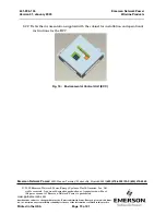
8.2.2 Refer the documentation supplied with the cabinet for installation and operational 

instructions for the ECC.

Fig. 15 :  Environmental Control Unit (ECC)

Содержание Mesa Sole

Страница 1: ...lectronic Sealed Architecture cabinet Fig 1 1 2 Reason For Reissue Whenever this practice is reissued the reason for reissue will be stated in this paragraph 1 3 Information Not Provided in this Practice Refer to other local practices or building codes as applicable for the correct methods tools and materials to be used in performing procedures not specifically described in this document Note The ...

Страница 2: ...bution and battery backup Note All power and alarm cables are provided with the MESA SOLE enclosures 2 1 3 The compact size of the MESA SOLE allows it to be wall pad or pole mounted For applications where the cabinet is to be pad mounted the optional base chamber must be ordered 2 1 4 The MESA SOLE cabinet provides a sealed internal environment where outside air and humidity are totally isolated f...

Страница 3: ...fting equipment The cabinet consists of an equipment chamber that houses the electronics an optional vented base chamber for housing batteries and an optional side mountable Customer Access Module 2 3 The MESA SOLE is designed to meet the following standards Bellcore GR 63 CORE Network Equipment Building System NEBS Requirements Physical Protection Issue 1 October 1995 Bellcore GR 487 CORE Generic...

Страница 4: ... Battery base for 60 Amp hr batteries 14 98 38 05 cm Total height with battery base installed 48 00 121 92 cm Depth 26 53 67 39 cm Width 33 13 84 14 cm without Customer Access Module 43 13 109 80 cm with Customer Access Module Weight Empty cabinet approximately 125 lbs 56 70 kg For batteries add approximately 200 lbs 90 72 kg For equipment add approximately 375 lbs 170 10 kg Fig 3 MESA SOLE Dimens...

Страница 5: ...inch 2 54 cm centers Each equipment mounting rail is bonded by contact through the cabinet chassis to the Master Ground Bar MGB The equipment mounting rails are designed to accept standard 12 inch 30 48 cm deep with 5 in 12 7 cm front offset mounted equipment 2 5 4 Vertical Rack space There is 25 inches 63 50 cm of vertical mounting space on side 1 and 25 inches 63 50 of vertical mounting space on...

Страница 6: ... 2009 Page 6 of 21 Proprietary Information Outside Plant Equipment for customer equipment This module is sealed from the outside environment by a right hand hinged door which is held in place by two 1 4 turn fasteners The 1 4 turn fasteners are opened using a 216 hex tool ...

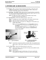
Страница 7: ...p 2 Place the tamper resistant wrench onto a security bolt Step 3 Rotate the wrench one quarter turn 90 degrees to toward the top or bottom of the cabinet Note A 1 4 turn is LEFT HAND if it is on the LH SIDE of the door To close the 1 4 turn rotation is to the LEFT The hinge is to the RIGHT A 1 4 turn is RIGHT HAND if it is on the RH SIDE of the door To close the 1 4 turn rotation is to the RIGHT ...

Страница 8: ...ehicles or pedestrians Select locations that will minimize accidental or intentional vandalism Consider the use of protective posts when the cabinet is located near parking areas where vehicles could back into the cabinet Do not place the cabinet in ditches or areas subject to flooding Place the cabinet at least 42 inches 106 68 cm away from any obstruction fence hedge etc If an area is subject to...

Страница 9: ...e packaging according to local practices DO NOT REMOVE THE CABI NET FROM IT S PALLET AT THIS TIME Note When ordered batteries are shipped on separate pallets from the cabinet 4 2 2 Inspect any moving parts mounting hardware connectors and electronic equipment If there is any damage notify your supervisor for further instructions 4 2 3 Check the packing slip to make sure all components ordered were...

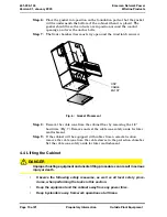
Страница 10: ...floor by removing the 1 4 hardware Fig 7 Remove and set the cable cone safely aside for later reattachment Step 9 If the cabinet will be equipped with cables from a remote location remove the cable cone from the cable sleeves in the protection chamber Set the cable cone safely aside for later reattachment 4 4 Lifting the Cabinet DANGER Improper hoisting equipment and unsafe lifting procedures can ...

Страница 11: ... the crane be alert for overhead obstructions that might interfere with move ment of the crane DO NOT ALLOW THE CABINET OR CRANE TO TOUCH ANY ELECTRICAL WIRING OR EQUIPMENT If the cabinet is to be moved while it is attached to the pallet such as in a turnkey staging area or temporary storage location lift it with a forklift vehi cle positioned at the long side of the pallet The forklift must be ra...

Страница 12: ...take up the slack with the crane DO NOT tighten the cables so that the pallet lifts The weight of the pallet will make it difficult to remove the bracket bolt Step 2 If installed use a 216 type tool to remove the OSP cable side base panel of the battery chamber Fig 9 Step 3 Remove the bolts from the pallet mounting bracket which secures the cabinet to the pallet MINIMUM LENGTH 8 FEET 2 4 m SLINGS ...

Страница 13: ...r bolts Make sure the cabinet is clear of the conduits in the foundation pad Step 5 Place the cabinet on the pad Loosen the slings so that the full weight of the cabinet is on the pad Check to be sure the cabinet is properly lined up on the pad Step 6 To secure the cabinet to the pad install 0 5 13 1 2 13 bolts with washers and lock washers into the bottom flange Tighten all bolts securely Step 7 ...

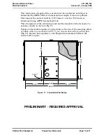
Страница 14: ...imeter of the cabinet Recommended pad dimensions 52 00 x TBD 132 08 cm x 138 43 cm 5 1 5 The overall dimensions of the pad template is 28 00 x 16 00 71 12 cm x 40 64 cm 5 1 6 Use a minimum of six inches 15 24 cm of sand or gravel as a base for the foundation pad This will level the location to accept the pad Refer to Fig 11 for the arrangement and size of the reinforcing mesh and the template in t...

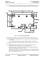
Страница 15: ...to 4 inches 101 6 mm as determined using ASTM test method C143 The arrangement of the reinforcing mesh and the template in the form prior to pouring concrete is shown in Fig 11 Square and level the template s on the stakes so the tops of the mounting plates are flush with or no more than 0 25 1 4 in 6 mm above the top of the pad Fig 12 Square the template s so the diagonal measurement between the ...

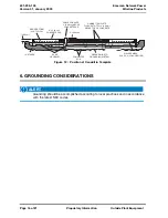
Страница 16: ...ed according to local practices and in accordance with the latest NEC codes CABLE CONDUITS 2 5 08 cm ABOVE CONCRETE PAD CABINET TEMPLATE FLUSH WITH TO 1 4 6 4 mm ABOVE TOP OF CONCRETE 2 5 08 cm 5 08 cm WOODEN FORM 2 x 6 TYPICAL 6 15 24 cm CONCRETE PAD WELDED MESH 6 X 6 X 4 4 4 GAUGE WIRE GROUND WIRE TO GROUNDING SYSTEM COMPACTED SOIL SAND OR GRAVEL 16 STAKES Figure 12 Position of Conduit in Templa...

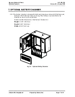
Страница 17: ...CHAMBER 7 0 1 The battery chamber is designed to hold one 60 amp hour string of 12Vdc front post batteries Four batteries make one string The batteries are installed in the chamber in one row of four batteries Interior usable dimensions of the battery chamber are Height 13 00 33 02 cm Depth 12 00 30 48 cm Width 20 00 50 8 cm Fig 13 Optional Battery Chamber ...

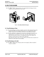
Страница 18: ...ons The exterior cooling air is never mixed with the air in the electronics chamber 8 1 2 The heat exchanger is equipped with an internal and external fan that can run independently of each other If one fan fails the other will keep operating The external fan draws exterior air through the bottom of the cabinet and exhausts it out into the air chamber in the cabinet top The internal fan draws inte...

Страница 19: ...r transmission without the prior consent of Emerson Network Power is prohibited www gotoemerson com Specifications subject to change without notice Emerson Network Power Energy Systems North Amer ica Inc disclaims any responsibility or liability for the use of the information contained in this practice Printed in the USA Page 19 of 21 8 2 2 Refer the documentation supplied with the cabinet for ins...

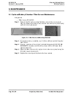
Страница 20: ...lter screen Set the nuts and access panel safely aside for later replacement Step 2 If compressed air is available use it to blow off dust and dirt from the filter screen Step 3 Prepare a solution of warm water and mild detergent DO NOT USE SOLVENTS Gently scrub the filter screen with a soft brush Set is safely aside to dry Step 4 When the filter screen is dry replace it onto the access panel usin...

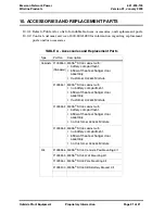
Страница 21: ...abinets F1009260 Standard MESA SOLE cabinet with battery compartment 650 watt heat exchanger door assembly Customer Access Module F1009261 MESA SOLE cabinet with no battery compartment 650 watt heat exchanger door assembly Customer Access Module F1009262 MESA SOLE cabinet with battery compartment 650 watt heat exchanger door assembly no Customer Access Module F1009263 MESA SOLE cabinet with no bat...

Отзывы: