background image

Communication System Manual


UPS System: HIPULSE E  

(Modbus/Jbus Interface) 


Description of Protocol 


(04/07)


Page 5-19  


5.13


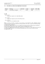
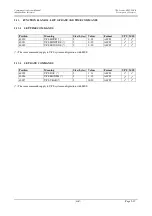
FUNCTION 06 AND 16: LIST OF DATE AND TIME COMMANDS 


5.13.1


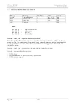
SET TIME COMMANDS 


Position 

Meaning 

Size (bytes)  Values 

Format 

UPS  MSS 

40020 

UPS HOUR (*) 

2  

0 : 23 

ASCII 


40021 

UPS MINUTES (*) 

0 : 59 

ASCII 


40022 

UPS SECONDS (*) 

0 : 59 

ASCII 


(*) The same commands apply to UPS system configuration with MSS. 


5.13.2


SET DATE COMMANDS 


Position 

Meaning 

Size (bytes)  Values  

Format 

UPS  MSS 

40025 

UPS DAY (*) 

2  

1 : 31 

ASCII 


40026 

UPS MONTH (*) 

1 : 12 

ASCII 


40027 

UPS YEAR (*) 

00:99 

ASCII   


(*) The same commands apply to UPS system configuration with MSS. 


Содержание Liebert HiPulse E Series

Страница 1: ... UP P PS S S S S SY Y YS S ST T TE E EM M M C Co om mm mu un ni ic ca at ti io on n M Ma an nu ua al l M MO OD DB BU US S J JB BU US S I In nt te er rf fa ac ce e F Fr ro om m 1 16 6 1 1 t to o 1 19 9 1 1 F FW W R Re el le ea as se e ...

Страница 2: ......

Страница 3: ... Customer Service Support department at the address shown below Emerson Network Power Ltd United Kingdom Customer Service and Support Department Fourth Avenue Globe Park Marlow Buckinghamshire SL71YG United Kingdom Telephone 44 1628 40 32 00 Fax 44 1628 40 32 03 Emerson Network Power Services Dpt Customer Service and Support Department Via Leonardo da Vinci 8 35028 Piove di Sacco PD Italy Help Des...

Страница 4: ...UPS System HIPULSE E Communication System Manual Modbus Jbus Interface Page iv ...

Страница 5: ...s entered with the Operator Panel 5 4 5 4 PANEL CONFIGURATION 5 5 5 4 1 Notes regarding PANEL CONFIGURATION REQUEST 5 5 5 4 1 1 UPS MSS Power Setting 5 5 5 4 1 2 UPS MSS Configuration Parameter 5 5 5 4 1 3 UPS MSS Status 5 5 5 4 1 4 Alarm Status 5 5 5 5 UPS MSS TIME 5 6 5 6 UPS MSS DATE 5 6 5 7 ALARM STATUS 5 7 5 7 1 Notes regarding Request for Alarm Status 5 7 5 8 MEASUREMENTS 5 11 5 8 1 Notes on...

Страница 6: ...UPS System HIPULSE E Communication System Manual Modbus Jbus Interface Pagina vi ...

Страница 7: ...enu will no longer be available once the optional MODBUS EPROM is installed Two way communication with the surrounding environment using the MODBUS protocol takes place over a serial line through the RS485 interface at the UPS System The information required to set up and use the MODBUS option included on the Operator Logic board of UPSs or MSS in the HIPULSE E is provided below The UPS System is ...

Страница 8: ...UPS System HIPULSE E Communication System Manual General Features Modbus Jbus Interface Page 1 2 04 07 ...

Страница 9: ...f load applied Battery parameters applies to UPS only battery voltage and current battery charge as a percentage Temperature applies to UPS only Battery Temperature C if the optional temperature sensor is being used machine status in terms of signals alarms UPS MSS settings in terms of UPS type single or three phase language on operator panel display This data is physically contained in a single s...

Страница 10: ...UPS System HIPULSE E Communication System Manual System Functions Modbus Jbus Interface Page 2 2 04 07 This page is left blank intentionally ...

Страница 11: ...nside of the UPS access door refer to Figure 3 3 or for MSS see Fig 3 4 protected by a metal cover HIPULSE E only and connected to the other electronic boards in the UPS MSS It connects the UPS MSS with a BMS through an RS485 serial line and a three way terminal board X4 on the bottom of the board As shown in figure 3 1 Figure 3 1 Operator Logic Board P N 4550005F 08I with MODBUS protocol for BMS ...

Страница 12: ...ULSE E Communication System Manual Mechanical Installation Modbus Jbus Interface Page 3 2 04 07 Figure 3 2 Location of Operator Logic Board P N 4550005F on the HIPULSE E UPS and connection with the Modbus network BMS ...

Страница 13: ...System Manual UPS System HIPULSE E Modbus Jbus Interface Mechanical Installation 04 07 Page 3 3 Figure 3 3 Location of Operator Logic Board P N 4550008I on the HIPULSE E MSS and connection with the Modbus network BMS ...

Страница 14: ...on of at least 0 25 mm 2 The cable must comply with the requirements of ANSI TIA EIA 485 A standards The RS 485 connection cable must finish at each end with a jumper inserted on the Operator board at position X25 1 2 in the figure below this must be done on UPS 1 and on the initial connection at the start of the Modbus network Figure 3 4 RS 485 Connection The following signals are present Pin Des...

Страница 15: ...ction The connection between UPS modules should be made using a two wire shielded cable with very thick copper braiding in which the shield forms a third constraining wire COM is COMPULSORY The wire must have a section of 0 25 mm 2 The length of each cable will depend on the position of the machines in the installation the total length should not exceed 1 km The RS 485 connection cable must finish...

Страница 16: ...Communication System Manual UPS System HIPULSE E Modbus Jbus Interface Electrical installation Page 3 6 04 07 This page is left blank intentionally ...

Страница 17: ...efer to the User Manual for more detailed information ENTER Used to confirm selection and go on to the next window If a parameter has been entered or selected it will be saved in memory when you press ENTER ESC ESC cancels the last action and returns to the previous window If pressed twice it will take you back to the first window Press ESC when entering data or parameters to exit without saving M...

Страница 18: ...lected sub menu A request for the numerical password will appear To enter the password use the UP key to scroll through values 0 through 9 for each digit and press DOWN to go on to the next digit When you have finished entering the password press ENTER and confirmation or an error message will appear For UPS Select NEXT PAGE and press ENTER For MSS Select NEXT PAGE and press ENTER For UPS Select P...

Страница 19: ...dow Select ID CRC JBUS and press ENTER Set user parameters to suit the type of installation Press ENTER to confirm settings Parameter Description ID Number identifying the address of the UPS MSS in the MODBUS JBUS RTU network Range 1 247 default 1 Assign a different identification number to each device in a multipoint connection CRC L H or H L default H L Note Select H L if the BMS uses CRC transm...

Страница 20: ...g settings complete the programming process by confirming all the data entered using the following window Select RESET PROTOCOL and press UP to select Y YES then press ENTER Warning If the user does not select RESET PROTOCOL initialisation will not take place and the selected protocol will not be applied Press ESC repeatedly to return to the Display window moving back through the various windows u...

Страница 21: ...General features of the MODBUS JBUS RTU protocol The Modbus Jbus RTU protocol is handled using the serial line managed directly by the Siemens 80C166M microcontroller which uses the RS485 interface This serial line may be used to set up a network of connected UPSs by connecting Operator Logic boards to one another see Fig 3 6 This function and all other settings already made to set up a network wi...

Страница 22: ... None 2 Even 5 3 Software Features of Communication Protocol The Panel board acts as a Slave meaning that it stays on standby awaiting commands coming in from the BMS Note Use of the MODBUS JBUS RTU excludes the connection with UPS network function in which a Master Panel queries panels of Slave units and permits communication with a Local Remote PC in the MODBUS JBUS RTU protocol none of the pane...

Страница 23: ... is positioned in the CRC register 3 The CRC register is shifted to the right by one bit toward the less significant bit LSB and a zero is put in the position of the most significant bit MSB The LSB is examined 4 If LSB 0 step 3 is repeated If LSB 1 an exclusive OR of the CRC register with the hexadecimal value A001 is applied 5 Steps 3 and 4 are repeated until 8 shifts have been carried out At th...

Страница 24: ...e and time request Function 03 Read Holding Register c Request for UPS alarm status Function 03 Read Holding Register d Request for values of current UPS measurements Function 03 Read Holding Register e Request for UPS programming settings Function 03 Read Holding Register f Request for Alarm History Function 03 Read Holding Register g UPS Alarm History command Function 06 Write Single Register h ...

Страница 25: ...om functioning with an incorrect power value when it is first turned on or programming data is reset To restore correct functioning set the correct power value and any other programming data required then restart the system 5 4 1 2 UPS MSS Configuration Parameter Note Rotating value for UPS 0x0 Single UPS 0x1 Parallel UPS with Internal Mains Static Switch 0x2 Parallel UPS with External Mains Stati...

Страница 26: ...uration with MSS Address Meaning Size bytes Range Resolution Format 40020 UPS HOURS 2 0 23 ASCII 40021 UPS MINUTES 2 0 59 ASCII 40022 UPS SECONDS 2 0 59 ASCII 5 6 UPS MSS DATE The UPS date request command is used to read the current date on the UPS The same commands apply to UPS system configuration with MSS Address Meaning Size bytes Range Resolution Format 40025 UPS DAY 2 1 31 ASCII 40026 UPS MO...

Страница 27: ...ITCH OPEN bit 4 RECTIF SWITCH OPEN bit 5 BATTERY C B OPEN bit 6 MANUAL BYPASS CLOSED bit 7 ECHOMODE bit 8 FAN FAILURE ALARM bit 9 CRASH LOAD OPTION bit 10 BYP ABSENT bit 11 BYP OVERVOLTAGE bit 12 BYP UNDERVOLTAGE bit 13 BYP FREQUENCY ERROR bit 14 BYP PHASE ROT ERROR bit 15 BYP SCR FAILURE Note Alarms 16 through 31 Meaning UPS MSS bit 0 BYPASS OFF bit 1 BYP OFF VIA REMOTE bit 2 LOAD ON BYPASS bit 3...

Страница 28: ...0 OUTPUT WAVEFORM ERR bit 11 INV FREQUENCY ERROR bit 12 INV PARALLEL ERROR bit 13 CONTACTOR FAILURE bit 14 NR INVERTERS NOT OK bit 15 PARALLEL BUS OPEN Note Alarms 48 through 63 Meaning UPS MSS bit 0 x UPS NOT ACTIVE bit 1 x UPS REDONDANCE bit 2 BATTERY UNDER TEST bit 3 BATTERY TEST FAILED bit 4 BATTERY ON LOAD bit 5 BATTERY END DISCH bit 6 BOOST TIME EXPIRED bit 7 DC BUS SLOW OVERVOL bit 8 DC BUS...

Страница 29: ... PAR PAG 1 bit 8 ERROR LRC PAR PAG 2 bit 9 ERROR LRC PAR PAG 3 bit 10 ERROR LRC ALARM HIS bit 11 ERROR LRC EVENT HIS bit 12 INTERNAL BATTERY LOW bit 13 ERR LRC RAM UPTIME bit 14 WATCH DOG RESET bit 15 ERR LRC RAM BATT Note Alarms 80 through 88 Meaning UPS MSS bit 0 LRC error in reset table bit 1 LRC error in panel parameters bit 2 Not used bit 3 LRC error in panel alarms bit 4 Not used bit 5 Not u...

Страница 30: ...UPS System HIPULSE E Communication System Manual Description of Protocol Modbus Jbus Interface Page 5 10 04 07 ...

Страница 31: ...0064 Percent Load NOTE 2 000 100 HEX 40065 Percent Load NOTE 2 000 100 HEX 40066 Batt Charge Percentage 2 000 100 HEX note 3 4 40067 Batt Time Remaining 2 Minutes HEX note 3 4 40068 Batt Temperature 2 0 1 C HEX note 2 4 NOTE ON FIRMWARE REL 19 1 are INVERTER PERCENT LOAD Values on which thermal overload are computed 5 8 1 Notes on Request for Measurement Status Note Measurements with values in a r...

Страница 32: ...e Page 5 12 04 07 Note Measurements not present on the MSS In certain cases measurements of given quantities have no significance when running on MSS but are significant when running on UPS In this case if the RTU Jbus Master Modbus requests these measurements the value returned will be 0xFFFF ...

Страница 33: ...s 2 190 210 HEX note 3 40089 Rated capacity 2 0 9999 Ah HEX note 3 40090 End of cell discharge 2 150 170 1 10 V HEX note 2 e 3 Pre alarm for end of 2 170 190 1 10 V HEX note 2 e 3 40091 cell discharge Res 1 10 Volt Maximum cell voltage 2 230 270 1 10 V HEX note 2 e 3 40092 Res 1 10 Volt 40093 Duration of battery test 2 00 99 min HEX note 2 e 3 40094 Battery test threshold 2 170 190 1 10 V HEX note...

Страница 34: ...charge x xx Volts Maximum cell voltage x xx Volts Battery test threshold of cell x xx Volts In some cases programming data values are not whole numbers In this case if the measurement is not a whole number it is multiplied by 100 before it is put into the Modbus Jbus RTU protocol buffer Note Measurements not present on the MSS In certain cases measurements of given quantities have no significance ...

Страница 35: ...0174 Active Power L1 Alarm Hist 2 1 kWatt HEX note 4 40175 Active Power L2 Alarm Hist 2 1 kWatt HEX note 4 40176 Active Power L3 Alarm Hist 2 1 kWatt HEX note 4 40177 Bypass Freq Alarm Hist 2 0 1 Hz HEX note 4 40178 Inv Freq Alarm Hist 2 0 1 Hz HEX note 4 40179 Vin L1 L2 Alarm Hist 2 1 Volt HEX 40180 Vin L2 L3 Alarm Hist 2 1 Volt HEX 40181 Vin L3 L1 Alarm Hist 2 1 Volt HEX 40182 V batt Alarm Hist ...

Страница 36: ...m buffer 0x3 Alarm empty Nota Alarm correspondence Refer to the notes on Alarm Status for information on correspondence of bits in the Word with alarms Note Measurements Refer to the notes on Measurement Status for information on notes regarding measurements in the Alarm History buffer Note Measurements not present on the MSS In certain cases measurements of given quantities have no significance w...

Страница 37: ...ointer to previous alarm or erase alarm history buffer command is given the 5F 08I board automatically sends commands for reading board 7H 09J in order to request the Alarm History buffer to which the pointer is currently set If the Master Jbus Modbus RTU sends a message requesting the selected alarm history during this time the 5F 08I board will respond with an 0x4 error code stating that the Sla...

Страница 38: ...mand value 0xAAAA Inverter ON command Note UPS value 0x5555 Rectifier OFF command value 0xAAAA Rectifier ON command MSS value 0x5555 Mains OFF command value 0xAAAA Mains ON command Note UPS value 0x5555 Mains OFF command value 0xAAAA Mains ON command MSS value 0xAAAA Reset MSS Alarms command Note value 0xAAAA Start Battery Test command Note value 0xAAAA Start Battery Charge command Note value 0xAA...

Страница 39: ...ng Size bytes Values Format UPS MSS 40020 UPS HOUR 2 0 23 ASCII 40021 UPS MINUTES 2 0 59 ASCII 40022 UPS SECONDS 2 0 59 ASCII The same commands apply to UPS system configuration with MSS 5 13 2 SET DATE COMMANDS Position Meaning Size bytes Values Format UPS MSS 40025 UPS DAY 2 1 31 ASCII 40026 UPS MONTH 2 1 12 ASCII 40027 UPS YEAR 2 00 99 ASCII The same commands apply to UPS system configuration w...

Страница 40: ... signifies that the requested function is not supported Error code 2 specified above is sent in response to a request for inexistent parameters with an address out of range address error By definition MODBUS will not permit holes in parameter addresses In response to a request for inexistent parameters or parameters with an address which falls between existing parameter addresses the value 0xFFFFH...

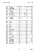
Страница 41: ...m 65 80 2 X X X X 40035 Alarm 81 88 2 X X X X 40040 Vout L1 L2 2 X X X X X 40041 Vout L2 L3 2 X X X X X 40042 Vout L3 L1 2 X X X X X 40043 Vout L1 N 2 X X X X X 40044 Vout L2 N 2 X X X X X 40045 Vout L3 N 2 X X X X X 40046 I out L1 2 X X X X X 40047 I out L2 2 X X X X X 40048 I out L3 2 X X X X X 40049 I out N 2 X X X X X 40050 Active Power L1 2 X X X X X 40051 Active Power L2 2 X X X X X 40052 Ac...

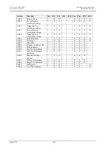
Страница 42: ...X X X 40083 rated output voltage Upper limit on 2 X X X X X X 40084 rated output voltage 40085 Rated frequency 2 X X X X X X 40086 Deviation 2 X X X X X X 40087 Slew Rate 2 X X X X X 40088 Number of battery cells 2 X X X X X 40089 Rated capacity 2 X X X X X 40090 End of cell discharge 2 X X X X X End of cell discharge 2 X X X X X 40091 pre alarm Maximum voltage 2 X X X X X 40092 per unit 40093 Bat...

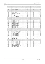
Страница 43: ...t L2 N Alarm Hist 2 X X X X X 40169 Vout L3 N Alarm Hist 2 X X X X X 40170 I out L1 Alarm Hist 2 X X X X X 40171 I out L2 Alarm Hist 2 X X X X X 40172 I out L3 Alarm Hist 2 X X X X X 40173 I out N Alarm Hist 2 X X X X X 40174 Active Power L1 Alarm Hist 2 X X X X X 40175 Active Power L2 Alarm Hist 2 X X X X X 40176 Active Power L3 Alarm Hist 2 X X X X X 40177 Bypass Freq Alarm Hist 2 X X X X X 4017...

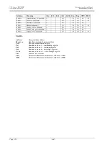
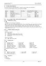
Страница 44: ...command 2 X X X X 40205 Battery charge command 2 X X X X 40206 Alarm reset command 2 X X X X X Legend Address Parameter data address Meaning Specifies meaning of parameter data Size Size of parameter data in bytes Fc3 Function code nr 3 read holding register Fc4 Function code nr 3 read input register Fc6 Function code nr 6 write single register Fc16 Function code nr 16 write multiple register Can ...

Отзывы: