background image

Inspection and Startup Checklist

28

Customer Alarms

If customer alarms are provided:
___ 1. With the FPC ON, simulate alarm operation by jumpering the appropriate low-voltage control 

terminals. (Refer to the control wiring installation drawing furnished with the unit.)

___ 2. Verify correct alarm annunciation by the Power Monitor Panel and/or by the Centralized 

Monitoring System.

3.4

Equipment Connection Check-Out of Units With Distribution Cables

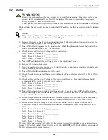
___ 1. Turn on main input power to the unit, then turn on the panelboard main output breaker(s).
___ 2. Individually turn on each branch circuit breaker and check the output voltage (also phase 

rotation, if a 3-phase circuit) at the receptacle or cable end.

___ 3. Turn OFF all branch circuit breakers and the panelboard main output circuit breaker(s).
___ 4. Connect the load equipment per equipment manufacturer’s specifications and 

recommendations.

___ 5. Turn on the panelboard main output breaker(s).
___ 6. Turn on branch circuit breakers to the load equipment.

___ 7. Verify that all load equipment operates properly.
___ 8. Replace all unit panels. After performing the inspection and start-up procedure described in 

3.0 - Inspection and Startup Checklist 

in this manual, complete the Start-Up and 

Inspection form furnished with the unit, sign the completed form and return it to:

Liebert Corporation
1050 Dearborn Drive
P.O. Box 29186
Columbus, Ohio 43229 USA

!

CAUTION

All loads should be disconnected or turned off before proceeding with the following steps.
For units with output distribution cables, be sure that NO output receptacles are connected to 

load equipment plugs and that the receptacles are not in contact with foreign objects.
Pay special attention to those output cables intended for direct wiring connection; the exposed 

conductor ends of these cables must not be in contact with each other or with any foreign 

objects.

!

CAUTION

Observe the power-up sequence recommended by the equipment manufacturer.

NOTE 

Warranty is not in effect until the inspection and startup form is received by the 

factory.

Содержание Liebert FPC

Страница 1: ...AC Power For Business Critical Continuity Liebert FPC User Manual 15 kVA 300kVA 3 Phase 50 60 Hz ...

Страница 2: ......

Страница 3: ...uctor for FPCs With Transformer 16 1 3 5 Output Power Connections 18 1 3 6 Control Wiring Connections 20 2 0 EQUIPMENT INSPECTION AND STARTUP 23 2 1 Internal Inspection 23 2 2 Startup 23 3 0 INSPECTION AND STARTUP CHECKLIST 25 3 1 Inspection 25 3 2 Startup 26 3 3 Monitoring System Check Out 27 3 4 Equipment Connection Check Out of Units With Distribution Cables 28 4 0 OPERATING INSTRUCTIONS 29 4 1...

Страница 4: ... shutdown circuit 20 Figure 15 Typical control wiring for units without monitoring 21 Figure 16 Typical control wiring for units with monitoring 22 Figure 17 Basic monitoring panel 30 Figure 18 Power monitor panel 30 TABLES Table 1 23 inch cabinet weight 3 Table 2 47 inch cabinet weight 4 Table 3 Liebert FPC heat output 6 Table 4 Suggested minimum input wire size data 12 Table 5 Main input circuit...

Страница 5: ...vice personnel should perform maintenance on the Liebert FPC system All voltage sources to the unit must be disconnected before inspecting or cleaning within the cabinet Lethal voltages exist within the equipment during operation Observe all warnings and cautions in this manual Failure to comply may result in serious injury or death Obtain qualified service for this equipment as instructed The mon...

Страница 6: ...unit to be rolled into place after it has been unbolted from the pallet The FPC should be kept on the shipping pallet until it has been moved by forklift as close as practical to its installation location Refer to the cabinet drawings furnished with the FPC for the unit s size and weight Typical cabinet dimensions and weights are shown in Figures 1 and 2 The route to the FPC s installation area sh...

Страница 7: ...t is equipped with distribution monitoring option Shaded areas indicate recommended clearance of 42 1067mm at front and rear for service access For units with bottom cable access clearance of 6 152mm below unit is recommended for cooling airflow and cable entry exit Dia location 3 4 19mm typical Floor Pedestals available from 6 152mm to 18 457mm 56 14mm diameter 4 holes typical 6 152mm 6 152mm 23 ...

Страница 8: ... recommended for service access if unit is equipped with distribution monitoring option Shaded areas indicate recommended clearance of 42 1067mm at front and rear for service access For units with bottom cable access clearance of 6 152mm below unit is recommended for cooling airflow and cable entry exit Overall Dimension 48 6 1235mm including side panels 78 1 2 1995mm 47 1194mm 36 4 925mm Unit Bas...

Страница 9: ...ipment location should employ the shortest output distribution cable runs consistent with logical equipment arrangement and allowance for expansion The FPC is intended for indoor installation in an area with ambient temperatures of 32 F to 104 F 0 C to 40 C with a relative humidity of 0 to 95 non condensing Bottom clearance is required for units with bottom entry exit of cables This clearance may ...

Страница 10: ... if unit is equipped with Liebert Distribution Monitoring Option Table 3 Liebert FPC heat output Unit kVA Full Load Heat Output BTU Hr kW 15 2 500 0 73 30 4 600 1 35 50 6 200 1 82 75 8 150 2 39 100 9 900 2 90 125 11 500 3 37 150 12 500 3 66 200 15 500 4 54 225 15 800 4 63 300 18 450 5 40 Minimum clearance of 6 152mm below unit is recommended for cable entry and exit Minimum clearance of 18 457mm a...

Страница 11: ...ut shaft assembly into or out of the pedestal base as required 3 Lock the height by tightening the jam nut against the pedestal base The pedestal may be anchored to the floor by means of the four holes in the base Locations of floor pedestals are shown in Figures 1 and 2 Figure 4 Floor pedestal details CAUTION Floor pedestals may be reverse assembled for shipping Before installation the pedestals ...

Страница 12: ...bution cabinet phase conductors are connected directly to the transformer terminals Phase A to X1 Phase B to X2 Phase C to X3 The FDC s neutral and ground conductors are connected to the FPC s neutral busbar and main ground busbar see unit wiring diagram for location For Liebert FPCs without transformers the distribution cabinet phase and neutral conductors are connected to the corresponding outpu...

Страница 13: ...nductors should be sized for no more than 2 voltage drop If operation at undervolt age conditions for extended periods of time is desired the input feeders must be oversized Typical conductor size data is shown in Table 4 All connections must comply with the NEC and all other applicable codes For units with a transformer the main input feeder should consist of 3 phase conductors and one safety gro...

Страница 14: ...nstallation Instructions 10 Figure 6 Electrical connection location for 47 1194mm cabinet Front view Figure 7 Electrical connection location for 47 1194mm cabinet Rear view FPC15000 Rev 0 FPC15000 Rev 0 ...

Страница 15: ... SqD I Line panelboard Front view Figure 9 Electrical connection location for 47 cabinet with SqD I Line panelboard Rear view FPC15002 Rev 0 Square D I Line Panelboard Detail B Output Ground Busbar Approx 1 4 Thick 1 75 44 4mm 1 75 44 4mm 88 22mm 88 22mm 3 28 83mm 3 28 83mm FPC15002 Rev 0 ...

Страница 16: ...0 3 0 AWG 139 175 2 0 AWG 240 125 175 2 0 AWG 380 79 100 2 AWG 76 100 2 AWG 400 75 100 2 AWG 72 90 2 AWG 415 72 90 2 AWG 70 90 2 AWG 480 63 80 4 AWG 600 50 70 4 AWG 75 208 215 300 350 kcmil 208 300 350 kcmil 240 186 250 250 kcmil 380 118 150 1 0 AWG 114 150 1 0 AWG 400 112 150 1 0 AWG 108 150 1 0 AWG 415 108 150 1 0 AWG 104 150 1 0 AWG 480 93 125 1 AWG 600 74 100 2 AWG 100 208 286 400 2 3 0 AWG 27...

Страница 17: ...power source possible 2 Ground conductors recommended to be insulated conductors run with power conductors for increased system performance Ground conductor minimum size per NEC Table 250 66 Input power feeder conduit may be used as the safety ground conductor When conduit is used adequate electrical continuity must be maintained at conduit connections to enclosures and throughout conduit run 3 In...

Страница 18: ...6 x 152 400A 3 pole power block with 1 2 13 studs on 1 3 4 44mm centers 750A ground busbar with two sets of 3 8 16 studs on 1 75 centers 35 x 22 x 6 889 x 559 x 152 750A phase busbars with 1 2 13 studs on 1 3 4 44mm centers 750A ground busbar with two sets of 3 8 16 studs on 1 3 4 44mm centers Table 7 Main input junction box without transformer electrical connections 5 wire Junction Box Size Inche...

Страница 19: ... feeder conduit Ground conductors must be at least the minimum size per NEC Table 250 66 Larger wire sizes may be used for increased system performance If the input power feeder conduit is used as a grounding conductor adequate electrical continuity must be maintained at all conduit connections CAUTION Using isolating bushings in a metal conduit run can be a safety hazard and is not recommended 1 ...

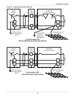
Страница 20: ...e grounding electrode conductor is run from the unit to the nearest effec tively grounded location listed in order of preference Building steel Metal water pipe Other made grounding electrode The grounding electrode conductor s size is based on the secondary circuit conductors Table 10 shows the minimum recommended grounding electrode conductor according to the NEC Table 250 66 Recommended methods...

Страница 21: ...electrode system Local grounding electrode conductor per NEC 250 28 Typical Liebert FPC with transformer grounding arrangement Signal reference grid if used Output Service Entrance Input J box if used Liebert FPC without transformer N G G Service entrance grounding electrode system Typical Liebert FPC without transformer grounding Signal reference grid if used Output N G N ...

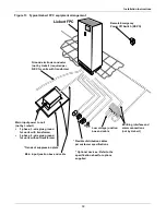
Страница 22: ...ng without imposing an energy use penalty during initial operation Balancing of loads is good design practice on any 3 phase system Accordingly each distribution panel is load balanced at the factory based on output branch circuit breaker sizes All additions to the sys tem should be arranged so as to preserve this balance For phase shifted multi output units to ensure proper harmonic current cance...

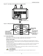
Страница 23: ...e 3 wire plus ground for units with transformer 3 phase 4 wire plus ground for units without transformer Main input power to unit not by Liebert Transient suppression plate Main input junction box and cable Flexible distribution cables per customer specifications Optional devices Refer to the specification sheet for options supplied Low voltage junction box and cable Building interface and alarm c...

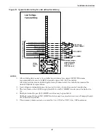
Страница 24: ...ser a typical requirement is that actuation of a single device REPO for example must shut down all power centers The low voltage control circuits of all standard Liebert FPC systems are designed to meet this requirement External Control Wiring Connections External control wiring connections for remote shutdown alarm and or monitoring are made to the low voltage junction box if used or to the low v...

Страница 25: ...ing devices are to be suitable for switching low current 24VDC Minimum recommended wire size is 18AWG stranded copper with 300V insulation All wiring and devices are field supplied except where noted See installation manual for detailed installation procedures 2 Low voltages terminal strip may be located in unit or low voltage control junction box 3 The total load on the 24VDC supply both N O and ...

Страница 26: ...1 All switching devices are to be suitable for switching low current 24VDC Minimum recommended wire size is 18AWG stranded copper with 300V insulation All wiring and devices are field supplied except where noted See installation manual for detailed installation procedures 2 Low voltages terminal strip may be located in unit or low voltage control junction box 3 The total load on the 24VDC supply b...

Страница 27: ...cklists Follow the detailed step by step checklist 3 0 Inspection and Startup Checklist when installing and starting up the Liebert FPC Initial System Startup A qualified electrician must be employed to perform the equipment inspection and startup Liebert system startup may be arranged by calling your local Liebert sales representative or Liebert Global Services In the United States call 1 800 LIE...

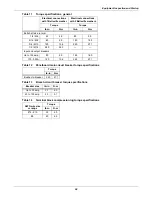
Страница 28: ...3 8 M10 120 13 6 240 27 1 1 2 M12 480 54 3 Input and output breakers Up to 150 amp 80 9 0 160 18 0 175 500A 120 13 6 240 27 1 Table 12 Panelboard main circuit breaker torque specifications Torque lb in N m Busbar to breaker 240 27 1 Table 13 Branch circuit breaker torque specifications Breaker size lb in N m Up to 30 amp 20 4 0 40 to 100 amp 20 5 1 Table 14 Terminal block compression lug torque sp...

Страница 29: ...ns for tightness Retorque if necessary ___ 7 Check all terminal block connections for tightness Retorque if necessary ___ 8 Check transformer mounting bolts for tightness Retorque if necessary ___ 9 Remove any foreign objects from the components or the interior area of the unit Make sure air passages on transformers are clear and free of debris ___ 10 Check that the intake and exhaust air screens ...

Страница 30: ...he main input breaker wait one minute If breaker trips OFF check for wiring errors including control connections Contact Liebert Global Services or the location factory representative for assistance ___ 12 Check the phase rotation at the line side terminals top of the panelboard main breaker s and any subfeed output circuit breaker s The rotation should be A B C left to right ___ 13 Check and reco...

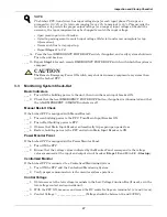
Страница 31: ...sured at the input and output circuit breaker Steps 10 and 13 in 3 2 Startup Centralized Monitor If the Liebert FPC is connected to a Centralized Monitoring System ___ 1 Turn ON the FPC and the Centralized Monitoring System ___ 2 Verify proper communication to the monitor system operation Control Voltage ___ 1 Obtain access to the low voltage terminals in the Low Voltage Junction Box if used or in...

Страница 32: ...n output breaker s ___ 6 Turn on branch circuit breakers to the load equipment ___ 7 Verify that all load equipment operates properly ___ 8 Replace all unit panels After performing the inspection and start up procedure described in 3 0 Inspection and Startup Checklist in this manual complete the Start Up and Inspection form furnished with the unit sign the completed form and return it to Liebert C...

Страница 33: ... can be turned OFF at each piece of load equipment or at the FPC s output distribution circuit breaker panels located behind the FPC s front door Turn OFF all unit output breakers then turn OFF the unit s main input circuit breaker To remove all power from the FPC turn OFF the building power to the FPC s input breaker or junction box 4 1 3 Normal System Turn ON Make certain all of the FPC s circui...

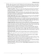
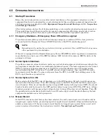
Страница 34: ...arm will automatically reset Figure 17 Basic monitoring panel 4 3 Power Monitor Panel Monitored Parameters A 4 x 20 character LCD is provided to indicate the input voltages line to line output voltages line to line and line to neutral output currents each phase neutral and ground output voltage THD output current THD crest factor K factor output kVA kW kWH power factor percent load and output freq...

Страница 35: ...phase currents has exceeded the pre set limit normally 95 of the unit s full load amp rating The overcurrent condition should be verified and corrective action taken In the absence of other procedures some of the output loads should be turned off to reduce unit loading If unbalanced phase currents exist some of the loads should be shifted from the higher loaded phase s to the lower loaded phase s ...

Страница 36: ...ses are in upper case terminated with a line feed 0Ah and carriage return 0Dh Table 15 ASCII interface default parameters Parameter Default Interface RS 232 using EIA voltage levels Baud rate 9600 Parity None Data bits 8 Stop bits 1 Terminator CR Hand shaking Not supported Structure Half duplex Echo OFF Change to receive after transmit 1 28 msec Minimum delay to transmit after receive 120 µsec Max...

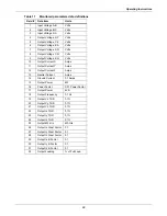
Страница 37: ... Amps 11 Output Current Y Amps 12 Output Current Z Amps 13 Neutral Current Amps 14 Ground Current 0 1 Amps 15 Output Power kW 16 Power Factor 0 01 Power Factor 17 Output Power kVA 18 Output Frequency 0 1 Hz 19 Output Vx THD 0 1 20 Output Vy THD 0 1 21 Output Vz THD 0 1 22 Output Ix THD 0 1 23 Output ly THD 0 1 24 Output Iz THD 0 1 25 Output kW Hrs kW Hrs 26 Output Ix Crest Factor 0 1 27 Output ly ...

Страница 38: ...life 5 2 1 Inspection Schedule It is difficult to establish a schedule for periodic cleanings because conditions vary from site to site Inspections after the first 24 hours 30 days and 6 months of operation should help determine a pattern for the inspection schedule Electrical connections and component mountings should be inspected after the first 24 hours 30 days and 6 months of operation Inspect...

Страница 39: ......
Страница 40: ...ebert Corporation All names referred to are trademarks or registered trademarks of their respective owners Technical Support Service Web Site www liebert com Monitoring 800 222 5877 monitoring emersonnetworkpower com Outside the US 614 841 6755 Single Phase UPS 800 222 5877 upstech emersonnetworkpower com Outside the US 614 841 6755 Three Phase UPS 800 543 2378 powertech emersonnetworkpower com En...

Отзывы: