Instruction Manual
D101351X012
646 Transducer
January 2015
15
Electrical
1. Ensure terminal lug connections from the control device to the transducer are of the correct polarity (refer to the
electrical connection procedures in the Installation section).
2. At the transducer, ensure that the milliampere DC signal is applied and that it is within the 4 to 20 milliampere
range.
Pneumatic
Provide a 4‐30 milliampere DC current source, supply pressure, and a gauge to monitor the output pressure when
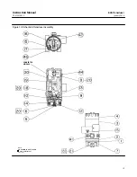
checking transducer operation. Refer to figure 10 for key number locations.
1. Ensure that supply pressure to the transducer is a consistent 1.4 bar (20 psig).
2. If a filter/regulator is used, ensure that it is working correctly. If not, ensure the dripwell is not plugged because of
excessive moisture accumulation. If necessary, drain off any moisture, and clean or replace the filter element.
3. Force the converter module to maximum output pressure with a 30 milliampere DC signal. Output pressure should
build up to the approximate value of the supply pressure.
4. When the input current is removed, the transducer output pressure should drop to less than 0.14 bar (2 psig). If it
does not, check to ensure the vent and exhaust air passageway is free from foreign material.
5. To inspect the relay assembly, refer to the relay maintenance procedures.
Converter Module Replacement
Removal
Refer to figure 10 for key number locations.
1. Remove the housing cap (key 4).
2. Note the location of the wires, then remove the electrical wiring from the terminal block mounted on the printed
wiring board.
3. Remove the two screws (key 19) and remove the converter module and wire guide (key 42) from the housing.
4. Inspect the O‐ring (key 18) and replace if necessary.
Replacement
1. Lubricate the O‐ring (key 18) with a lubricating compound such as key 20 before replacing the converter module in
the housing.
2. Insert the converter module and wire guide (key 42) into position in the housing (key 3). Replace the two screws
(key 19) and tighten them.
3. Replace the electrical wiring removed in step 2 of the removal procedures. Do not overtighten the terminal screws.
Maximum torque is 0.45 N
S
m (4 lbf
S
in).
4. Electrically calibrate the module following the procedures in the Calibration section.
5. Replace the housing cap (key 4).


